Method and system for controlling temperature of engine coolant

A technology of engine coolant and temperature control method, which is applied in the direction of engine cooling, coolant flow control, engine components, etc., can solve the problems of water temperature shock, difference, and long response time of the execution unit, so as to achieve efficient water temperature control and fuel Low economy, avoid high temperature effect

Active Publication Date: 2018-01-23
CHERY AUTOMOBILE CO LTD
View PDF10 Cites 8 Cited by
  • Summary
  • Abstract
  • Description
  • Claims
  • Application Information

AI Technical Summary

Problems solved by technology

[0004] However, due to the complex operating conditions of the engine and the many interference factors of the controlled object in the traditional engine thermal management system, and the long response time of the execution unit, the control of the engine coolant temperature often has a large gap with the target water temperature. In particular, when the engine operating conditions change greatly, the actual water temperature tends to fluctuate greatly
In addition, the target water temperature algorithm based on engine speed, load, vehicle speed, and intake air temperature also has more redundant calculations and mismatches in engine operating conditions. Under various environments and conditions, the target water temperature cannot be at The temperature at which the engine works best
In view of this, some engine thermal management systems adopt the control method of dual water temperature sensors to increase the method of collecting the water temperature of the radiator all the way to achieve the accuracy of the target water temperature control, but this kind of system undoubtedly increases the complexity of the system and the product. cost

Method used


Image

  • Method and system for controlling temperature of engine coolant
  • Method and system for controlling temperature of engine coolant

Examples


Embodiment Construction

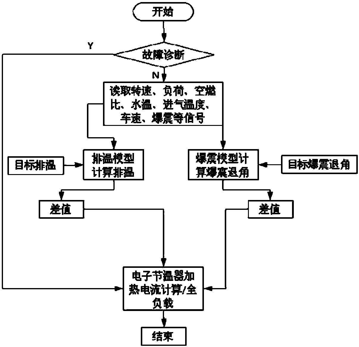
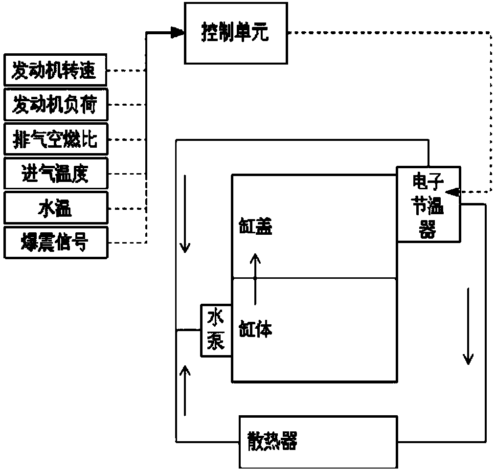
[0025] The present invention replaces the conventional target water temperature calculated based on parameters such as engine speed, load, intake air temperature and vehicle speed according to the engine target exhaust temperature and target knock relief angle, and the exhaust temperature calculated by the exhaust temperature model and the knock model of the electronic control system. Compare the parameters of the temperature and detonation angle to judge the combustion state of the engine. If the engine exhaust temperature and detonation angle are higher than the target exhaust temperature and detonation angle, the electronic thermostat will be energized. The value size is controlled.

[0026] In addition, through the mechanical thermostat function of the electronic thermostat, combined with the engine running state, after logical judgment, the temperature adjustment function of the mechanical thermostat is given priority, so that the engine is in the best working temperature ...


PUM


Abstract

The invention discloses a method for controlling the temperature of engine coolant, and aims to achieve the purpose. According to the technical scheme, the method for controlling the temperature of the engine coolant comprises the following steps: step 1, carrying out automatic system checking; step 2, acquiring an engine rotating speed signal, an engine load signal, an exhaust air-fuel ratio signal, an intake air temperature signal, a water temperature signal, a vehicle speed signal and an engine knocking signal in real time; step 3, establishing an exhaust temperature model and an engine knocking model; step 4, calculating the exhaust temperature condition of an engine in real time by the exhaust temperature model, and calculating the condition of an engine knocking receding angle by theengine knocking model; and step 5, outputting a control signal to an electronic thermostat according to calculated results. By the method, direct relation between the temperature of the coolant and the combustion state of the engine can be established, accurate control is implemented, the fuel economy is low, meanwhile, the temperature of the engine is prevented from being over high, parts of theengine are protected, and the electronic thermostat controls water temperature efficiently, accurately and stably.

Description

technical field [0001] The invention belongs to the field of internal combustion engines for vehicles, and relates to an engine cooling system, in particular to a cooling liquid control system and method with an electronic thermostat. Background technique [0002] Engine thermal management technology is currently one of the important technical means to increase engine power density, improve economy and reliability, and is also an important direction for the development of intelligent engine control technology. Advanced engine thermal management technology can make the engine work in the optimal temperature range under different working conditions, thus providing indicators such as engine fuel economy, power performance, car ride comfort and emissions. [0003] Engine intelligent thermal management system is generally composed of electric water pump, fan, electronic thermostat, control unit (ECU) and other components, and the control system adopts closed-loop feedback control...

Claims


Application Information

Patent Timeline
Patent Type & Authority Applications(China)
IPC IPC(8): F01P7/16
Inventor 贾志超
Owner CHERY AUTOMOBILE CO LTD
Why Eureka
Try Eureka