Magnetofluid sealing device for high vacuum

A magnetic fluid sealing, high vacuum technology, applied in the direction of engine sealing, engine components, mechanical equipment, etc., can solve the problem of low pressure resistance, achieve good high vacuum sealing effect, save manufacturing costs, and reduce processing difficulty.

Active Publication Date: 2018-01-23
GUANGXI UNIVERSITY OF TECHNOLOGY
View PDF8 Cites 7 Cited by
  • Summary
  • Abstract
  • Description
  • Claims
  • Application Information

AI Technical Summary

Problems solved by technology

[0005] The purpose of the present invention is to provide a magnetic fluid sealing device for high vacuum, so as to solve the problems of low pressure resistance existing in the existing sealing device, so that the sealing technology can be successfully applied in high vacuum and other fields

Method used


Image

  • Magnetofluid sealing device for high vacuum

Examples


Embodiment Construction

[0028] The present invention will be further described below in conjunction with accompanying drawing.

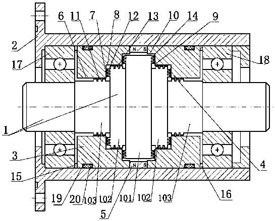
[0029] like figure 1 As shown, the magnetic fluid sealing device for high vacuum includes a stepped shaft 1, a casing 2, a left pole piece 3, a right pole piece 4, and a permanent magnet ring 5, and the stepped shaft 1 is set inside the casing 2;

[0030] The stepped shaft 1 includes an intermediate shaft 101 with the largest diameter and multiple sets of secondary shafts with successively decreasing diameters. The secondary shafts are arranged along the side of the intermediate shaft 101, and the middle radial section of the intermediate shaft 101 is The boundary is left and right symmetrical;

[0031] The inner wall of the housing 2 is provided with a permanent magnet ring 5 at a position corresponding to the outer circle of the intermediate shaft 101, and there is a gap between the permanent magnet ring 5 and the outer circle of the intermediate shaft 101; the left pole...


PUM


Abstract

The invention relates to the field of mechanical engineering sealing, in particular to a magnetofluid sealing device for high vacuum. The magnetofluid sealing device comprises a stepped shaft, a shell, a left pole shoe, a right pole shoe and a permanent magnet ring. The stepped shaft comprises a middle shaft with the maximum diameter and a plurality of sets of secondary shafts with the sequentially reduced diameters. The permanent magnet ring is arranged at the position, corresponding to the outer circle face of the middle shaft, of the inner wall of the shell. The left pole shoe and the rightpole shoe are arranged on the two sides of the permanent magnet ring and are symmetric. The end face and the annular face of the left pole shoe and the end face and the annular face of the right poleshoe correspond to the outer circle faces and the end faces of the middle shaft and the secondary shafts correspondingly. The end face of the middle shaft and the outer circle faces and the end facesof the secondary shafts are each provided with pole teeth which extend in the radial direction or the axial direction, gaps are reserved between the pole teeth and the corresponding end faces and theannular faces of the left pole shoe and the right pole shoe, and the magnetofluid is located in the gaps. By means of the magnetofluid sealing device for high vacuum, the problem that an existing sealing device is relatively low in pressure resistance and other problems can be solved.

Description

technical field [0001] The invention belongs to the field of mechanical engineering sealing, and in particular relates to a magnetic fluid sealing device for high vacuum. Background technique [0002] When the magnetic fluid sealing technology is applied in a high vacuum environment, the unreasonable design of the ordinary magnetic fluid sealing structure often leads to the failure of the seal. Therefore, improving the pressure resistance of the magnetic fluid sealing under high vacuum conditions is one of the hot issues in current research. [0003] One of the methods to improve the pressure resistance performance of the magnetic fluid seal in a high vacuum environment is to improve the magnetic fluid seal structure, such as the sealing device described in reference 1 (the patent with the publication number CN204805552U) and the sealing device described in the reference 2 (the patent with the publication number CN104948744A Patent) described sealing device. Although the ex...

Claims


Application Information

Patent Timeline
Patent Type & Authority Applications(China)
IPC IPC(8): F16J15/43
CPCF16J15/43
Inventor 杨小龙陈帆谢国进孙彭郝付祥
Owner GUANGXI UNIVERSITY OF TECHNOLOGY
Why Eureka
Try Eureka