
Electric three-way valve and refrigeration equipment

An electric three-way valve and valve body technology, applied in multi-way valves, mechanical equipment, valve details, etc., can solve the problem that the transmission cannot be meshed normally or stuck, the center distance is too large, and the coaxiality of the two shafts is difficult to guarantee. And other issues

Active Publication Date: 2018-01-23
ZHEJIANG SANHUA INTELLIGENT CONTROLS CO LTD
View PDF4 Cites 1 Cited by
  • Summary
  • Abstract
  • Description
  • Claims
  • Application Information

AI Technical Summary

Problems solved by technology

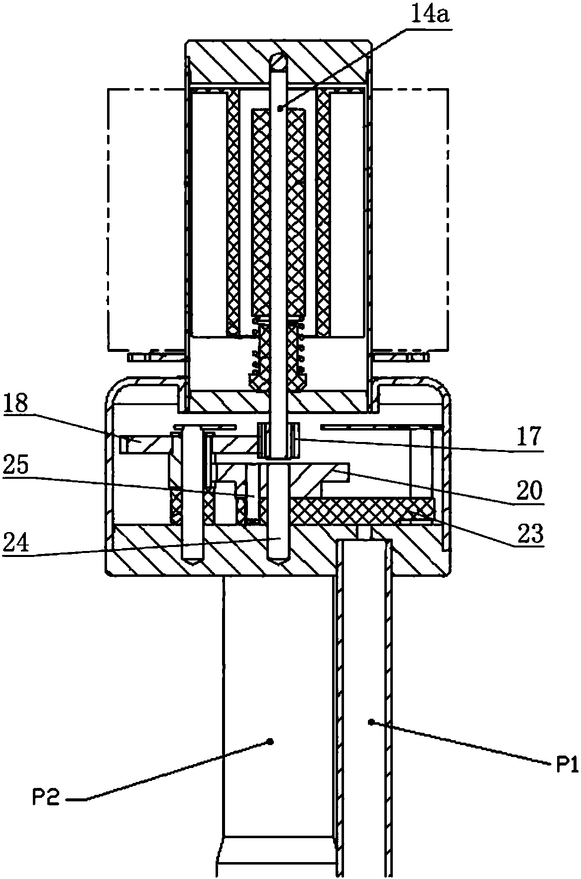
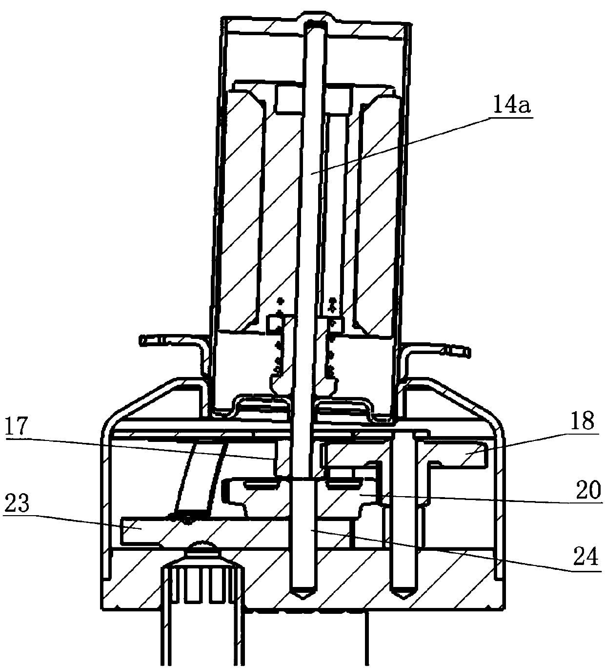
As a result, the center-to-center distance between the power gear 17 and the reduction gear 18 is relatively large, and the manufacturing process cost of related parts is relatively high during production. Normal engagement or seizure (see figure 2 )

Method used


Image

  • Electric three-way valve and refrigeration equipment
  • Electric three-way valve and refrigeration equipment
  • Electric three-way valve and refrigeration equipment

Examples


Embodiment Construction

[0029] The core of the present invention is to ensure the coaxiality between the gears by installing the power gear and the execution gear on the same central shaft, so as to eliminate the phenomenon that the gear shafts cannot be meshed or stuck due to poor coaxiality of the gear shafts.

[0030] In order to enable those skilled in the art to better understand the solution of the present invention, the present invention will be further described in detail below in conjunction with the accompanying drawings and specific embodiments.

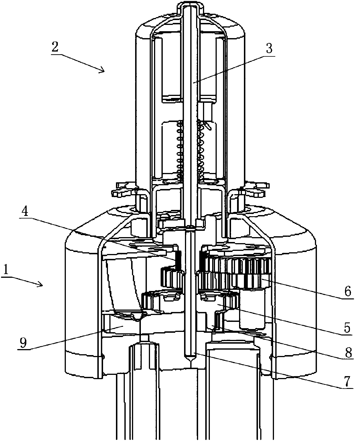
[0031] Please refer to image 3 , Figure 4 , image 3 It is a cut-away schematic diagram of a specific embodiment of the electric three-way valve provided by the present invention; Figure 4 It is a cross-sectional view of the power gear and the execution gear installed on the central shaft.

[0032] In a specific embodiment, the electric three-way valve provided by the present invention is mainly used in refrigeration equipment, especially i...


PUM


Abstract

The invention discloses an electric three-way valve and refrigeration equipment. The electric three-way valve comprises a valve body (1) and a coil (2). A power gear (4) and an execution gear (5) arearranged inside the valve body (1). The power gear (4) is driven by a rotor spindle (3) of the coil (2) and is further in meshing transmission with the execution gear (5) through a reduction gear (6).The execution gear (5) is installed on a center shaft (7) and used for driving a sliding block (9) to achieve flow path switching. The power gear (4) and the execution gear (5) are installed on the center shaft (7) together and are further distributed up and down in a spaced mode. According to the electric three-way valve, the power gear and the execution gear are located on the same center shaftand are further connected through the reduction gear, the gear coaxiality is greatly enhanced in production, and the phenomenon that normal meshing or clamping cannot be conducted due to the poor gear-shaft coaxiality is effectively avoided.

Description

technical field [0001] The invention relates to the technical field of valves, in particular to an electric three-way valve used in refrigeration equipment for controlling on-off and flow direction of refrigerant. The present invention also relates to refrigeration equipment provided with the electric three-way valve. Background technique [0002] At present, the three-way valves used in refrigeration equipment, especially the electric three-way valves in the heat pump air-conditioning pipeline, mostly control the on-off and flow direction of the refrigerant through the slider switching in the valve. [0003] The electric three-way valve is mainly composed of a valve body and a coil. The valve body has three valve ports. The direction of the magnetic rotor can be clockwise or counterclockwise, so that the magnetic rotor part rotates in the direction of the force. A series of gear transmissions in the valve body transmit the force to the slider. Switching between the two va...

Claims


Application Information

Patent Timeline
Patent Type & Authority Applications(China)
IPC IPC(8): F16K11/074F16K31/06F16K31/53
Inventor 不公告发明人
Owner ZHEJIANG SANHUA INTELLIGENT CONTROLS CO LTD
Learn More