Correction device and correction method for 1X optical sight with image display function

An image display and correction device technology, applied in the field of scopes, can solve the problems of magnification error, waste, magnification and design value deviation, etc., to achieve the effect of ensuring sealing, simple design, and accurate magnification

Pending Publication Date: 2018-01-23
江苏北方湖光光电有限公司
View PDF3 Cites 3 Cited by
  • Summary
  • Abstract
  • Description
  • Claims
  • Application Information

AI Technical Summary

Problems solved by technology

Generally, the magnification Γ of the sight with image display generally depends on the magnification Γ1 of the optical system and the magnification Γ2 of the electronic circuit. In general, the optical components and mechanical parts of the optical system may cause a certain deviation between the magnification and the design value. According to According to the optical design manual and the design experience of similar optical products, the maximum error of the magn

Method used


Image

  • Correction device and correction method for 1X optical sight with image display function
  • Correction device and correction method for 1X optical sight with image display function

Examples


Example Embodiment

[0024] The preferred embodiments of the present invention will be described in detail below with reference to the accompanying drawings.

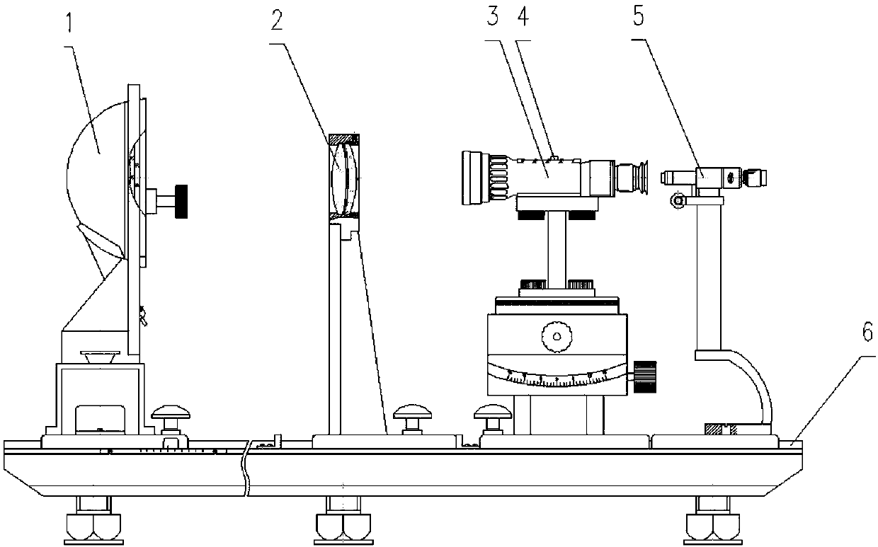
[0025] In order to achieve the purpose of the present invention, such as figure 1 As shown, in one of the embodiments of the present invention, a 1 with image display is provided X The correction device of the scope, including the optical bench 6, the reticle assembly 1, the collimating objective lens 2, the scope mounting frame, the rotary encoder 4 and the theodolite 5, the reticle assembly 1, the collimating objective lens 2, the scope mounting frame and The theodolite 5 is sequentially arranged on the optical bench 6 along a straight line, and the rotary encoder 4 is connected with the movement assembly of the sight 3.

[0026] Compared with the prior art, the design of the adjustment environment is simpler and the magnification ratio is more accurate in this embodiment. The adjustment does not need to disassemble the product, but can be real...


PUM


Abstract

The invention discloses a correction device and a correction method for a 1X optical sight with an image display function. The correction device comprises an optical bench, a graduation component, a collimator objective, an optical sight mounting rack, a rotary encoder and a theodolite. The graduation component, the collimator objective, the optical sight mounting rack and the theodolite are sequentially arranged on the optical bench in the direction of a straight line, and the rotary encoder is connected with a movement component of the optical sight. Compared with the prior art, the correction device and the correction method have the advantages that the calibration environment is designed relatively simply, the multiplying power is relatively accurate, a product does not need to be disassembled during calibration, calibration can be realized only through the rotary encoder on the optical sight, and thus the leakproofness of the product and the consistency of product adjustment are guaranteed.

Description

technical field [0001] The invention belongs to the field of scope technology, and in particular relates to a 1 sight with image display X A correction device and a correction method for a sight. Background technique [0002] With the development of new high-precision sniper systems and the development of tandem sights, 1 X The scope design is more and more widely used. Generally, the magnification Γ of the sight with image display generally depends on the magnification Γ1 of the optical system and the magnification Γ2 of the electronic circuit. In general, the optical components and mechanical parts of the optical system may cause a certain deviation between the magnification and the design value. According to According to the optical design manual and the design experience of similar optical products, the maximum error of the magnification can reach 5%, and it is difficult to adjust the magnification to 1 by general mechanical adjustment means. X , and waste more manpow...

Claims


Application Information

Patent Timeline
IPC IPC(8): F41G1/14F41G1/16
Inventor 邱卫根徐爱东朱家乙王威高赫谢佳丽刘昊微周智慧李业勋
Owner 江苏北方湖光光电有限公司
Why Eureka
Try Eureka