Multi-ocular stereoscopic vision three-dimensional scanning method and system

A technology for multi-eye stereo vision and three-dimensional scanning, applied in the field of three-dimensional scanning methods and systems for multi-eye stereo vision, can solve problems such as missing point cloud data, small geometric feature sizes, and inability to measure parts, so as to improve scanning efficiency and scanning accuracy, data processing algorithm optimization, and the effect of solving blind spots

Inactive Publication Date: 2018-01-23
SHENZHEN UNIV
View PDF15 Cites 22 Cited by
  • Summary
  • Abstract
  • Description
  • Claims
  • Application Information

AI Technical Summary

Problems solved by technology

However, the size of corresponding geometric features is small, parts with large free-form surfaces cannot be measured, and the scanning time is long and expensive
[0005] (2) Non-contact scanning mainly adopts computer vision technology, using binocular or multi-eye vision system for scanning, its accuracy is suitable and the structure is simple, because the traditional binocular stereo vision uses passive technology measurement, it cannot effectively solve the problem of repetition in the image areas, low-texture areas, similar-texture areas, etc., and the structured light method can solve the mismatch problem very well, but for objects with complex surfaces (objects with four corners or polyhedrons with complex surfaces) need Repeat scan multiple times
For the 3D laser scanning system using monocular or binocular stereo vision, the longitudinal point cloud information of the object surface can only be obtained from one angle, but there will be scanning blind spots for curved surface objects with complex surface shapes or partially occluded objects , leading to the loss of some point cloud data, which greatly increases the scanning time and data processing time of the system

Method used


Image

  • Multi-ocular stereoscopic vision three-dimensional scanning method and system
  • Multi-ocular stereoscopic vision three-dimensional scanning method and system
  • Multi-ocular stereoscopic vision three-dimensional scanning method and system

Examples


Embodiment Construction

[0056] In order to have a clearer understanding of the technical features, purposes and effects of the present invention, the specific implementation manners of the present invention will now be described in detail with reference to the accompanying drawings.

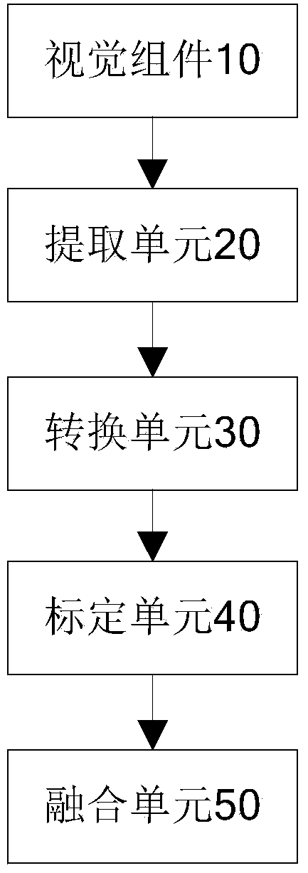
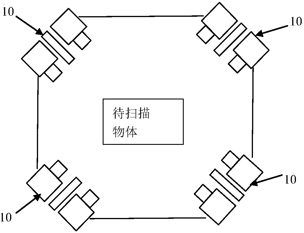
[0057] figure 1 A three-dimensional scanning system with multi-eye stereo vision in some embodiments of the present invention is shown, which is used to perform omni-directional lateral scanning on the surface of an object to be scanned from different viewing angles. The three-dimensional scanning system of multi-eye stereo vision in this embodiment includes a vision component 10, an extraction unit 20, a conversion unit 30, a calibration unit 40, a fusion unit 50, and a lifting platform (not shown), wherein the vision component 10 is used to treat Scan the object to perform three-dimensional scanning and obtain the light band image group, the lifting platform is used to carry the visual component 10 to move up and down...


PUM


Abstract

The invention discloses a multi-ocular stereoscopic vision three-dimensional scanning method and system. The method comprises the steps that S1: light band image groups are acquired by at least threegroups of vision components arranged around an object to be scanned and positioned at the same horizontal height, and each light band image group includes a left light band image and a right light band image; S2: the light band center of the left light band image and the right light band image is extracted; S3: the light band center is converted to the intra-group three-dimensional coordinate data; S4: joint calibration is performed and all the intra-group three-dimensional coordinate data are converted to the same coordinate system so as to obtain the world coordinate system data; and S5: point cloud integration is performed through combination of the world coordinate system data of all the horizontal weight so as to obtain the three-dimensional point cloud data of the object to be scanned. According to the multi-ocular stereoscopic vision three-dimensional scanning method and system, omnibearing transverse scanning is performed on the surface of the object to be scanned from different perspectives by at least three groups of vision components so that the blind area problem of scanning can be effectively solved, and the scanning efficiency and the scanning accuracy of the system can be enhanced.

Description

technical field [0001] The invention relates to the field of three-dimensional scanning, in particular to a three-dimensional scanning method and system for multi-eye stereo vision. Background technique [0002] Three-dimensional scanning is one of the popular technologies in recent years. Because of its simple structure and high precision, it has been widely used in 3D scanning, industrial measurement and other fields. [0003] At present, there are two types of scanning of 3D point clouds: contact and non-contact: [0004] (1) Contact scanning is mainly used in three-dimensional coordinate measurement, which has high precision and strong reducibility. However, the size of corresponding geometric features is small, and parts with large free-form surfaces cannot be measured, and the scanning time is long and expensive. [0005] (2) Non-contact scanning mainly adopts computer vision technology, using binocular or multi-eye vision system for scanning, its accuracy is suitabl...

Claims


Application Information

Patent Timeline
Patent Type & Authority Applications(China)
IPC IPC(8): G01B11/00
Inventor 徐渊王亚洲边育心周建华
Owner SHENZHEN UNIV
Why Eureka
Try Eureka