Numerical control milling machine cutter breaking monitoring method

A CNC milling and tool breaking technology, applied in the field of CNC, can solve the problems of affecting the processing quality and processing efficiency, excessive cutting force, and milling cutter breakage, so as to improve quality and customer satisfaction, and improve customer problems caused by missed milling. Complaints, the effect of saving manpower and material resources

Inactive Publication Date: 2018-01-23
SHANGHAI KAISER ELECTRONICS
View PDF6 Cites 1 Cited by
  • Summary
  • Abstract
  • Description
  • Claims
  • Application Information

AI Technical Summary

Problems solved by technology

[0002] In the process of CNC milling machine processing, excessive cutting force, tool aging and other reasons may cause the milling cutter to break
If the tool breakage cannot be detected in time, it will affect the processing quality and processing efficiency
After the equipment breaks the tool and alarms, it cannot effectively monitor whether the on-site operators are dealing with the products affected by the broken tool according to the requirements, and the problem of missed milling caused by the broken tool often occurs, resulting in customers often complaining about the missed milling problem caused by the broken tool

Method used


Image

  • Numerical control milling machine cutter breaking monitoring method
  • Numerical control milling machine cutter breaking monitoring method
  • Numerical control milling machine cutter breaking monitoring method

Examples


Embodiment Construction

[0023] The following describes a preferred embodiment of the present invention with reference to the accompanying drawings, which demonstrates that the present invention can be implemented, and can fully introduce the present invention to those skilled in the art, so that its technical content is clearer and easier to understand. The present invention can be embodied in many different forms of embodiments, and its scope of protection is not limited to the embodiments mentioned herein. The drawings and descriptions herein are illustrative rather than restrictive in nature. In the drawings, components with the same structure are denoted by the same numerals, and components with similar structures or functions are denoted by similar numerals.

[0024] The present invention will be further described below in conjunction with the accompanying drawings and embodiments.

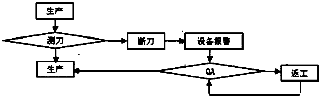
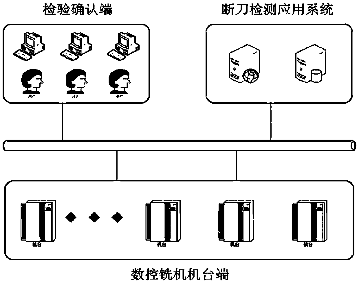
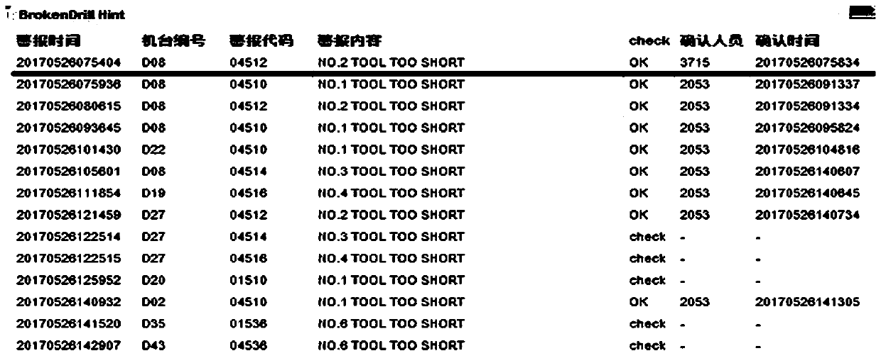
[0025] A preferred embodiment of the present invention provides a method for monitoring tool breakage of a CNC mi...


PUM


Abstract

The invention provides a numerical control milling machine cutter breaking monitoring method comprising the following steps that S1: a cutter measurer is installed on the cutter shaft of a milling machine, and the cutter measurer is corresponding to the cutter shaft in a one-to-one way; S2: a cutter measurement circuit is connected, and the situation of cutter breaking is judged by one signal given by on/off of the cutter measurement circuit; S3: if a power supply signal appears, the judgment result indicates the situation of cutter breaking; or the judgment result indicates no situation of cutter breaking; S4: the power supply signal is tracked and recorded and machine alarm prompting is given; S5: the record is searched for every period of time and the cutter breaking alarm signal is analyzed and identified; S6: the identified information is transmitted to the monitoring computer side; S7: the quality inspection personnel receives the information and performs on-site processing; andS8: the quality inspection personnel completes processing and then returns to the computer side for confirmation so that processing is completed. According to the numerical control milling machine cutter breaking monitoring method, the quality of the product and the customer satisfaction can be enhanced and the manpower and material resources for handling the customer complaint can be saved.

Description

technical field [0001] The invention relates to the technical field of numerical control, in particular to a method for monitoring tool breakage of a numerical control milling machine. Background technique [0002] During the machining process of CNC milling machine, excessive cutting force, tool aging and other reasons may cause the milling cutter to break. If the tool breakage cannot be detected in time, the processing quality and processing efficiency will be affected. After the equipment breaks the tool and alarms, it cannot effectively monitor whether the on-site operators are dealing with the products affected by the broken tool according to the requirements, and the problem of missed milling caused by the broken tool often occurs, causing customers to often complain about the missed milling problem caused by the broken tool. Contents of the invention [0003] In order to solve the above problems, the present invention provides a method for monitoring a broken tool ...

Claims


Application Information

Patent Timeline
Patent Type & Authority Applications(China)
IPC IPC(8): G05B19/4065
Inventor 杜景春郑玉柱
Owner SHANGHAI KAISER ELECTRONICS
Why Eureka
Try Eureka