An u-iron frame type straightening drum

A channel steel frame and straightening technology, applied in the field of straightening cylinders, can solve the problems of difficult processing, difficult to discharge dust of the straightening cylinder, troublesome operation, etc., and achieve the effects of long service life, good dust discharge performance and simple main structure

Inactive Publication Date: 2010-06-02
龙乐武
View PDF1 Cites 0 Cited by
  • Summary
  • Abstract
  • Description
  • Claims
  • Application Information

AI Technical Summary

Problems solved by technology

The square hole of the straightening block installed on the straightening cylinder is 30mm×30mm square, and there are Φ38mm adjusting screws on both sides of the straightening block. Because the teeth distance between the adjusting screws on both sides and the straightening cylinder square hole screw is limited, there are only four points at the position of 30mm. Contact, there is no tooth pitch on the four corners of the square hole. After the machine has been used for a period of time, the square hole screw in the straightening cylinder will "slip", causing the whole screw to be scrapped, and the straightening cylinder cannot be used, which brings unnecessary economic losses to the user.
[0010] During the use of the machine, there is too much oxidized dust on the surface of the steel bar, which makes it difficult to discharge the dust in the center hole of the straightening cylinder. Especially when straightening the steel bar in rainy days, because the temperature of the straightening cylinder is high during operation, water droplets and oxidized dust will straighten the block The adjustment screw is solidified and burned to death, causing the straightening cylinder straightening block screw to twist illegally, which brings great trouble to the operation
[0011] The structure of the straightening cylinder is complicated, and the processing is extremely difficult. It needs multiple production machinery and equipment from professional manufacturers to complete the processing, resulting in high production costs.

Method used


Image

  • An u-iron frame type straightening drum
  • An u-iron frame type straightening drum
  • An u-iron frame type straightening drum

Examples


Embodiment 1

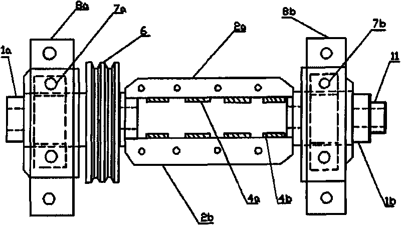
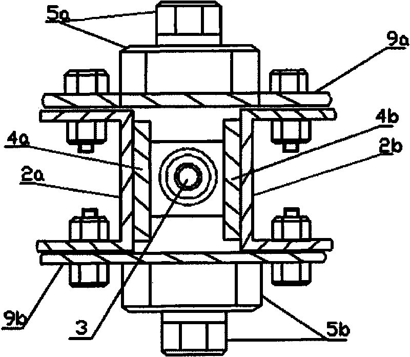
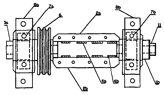
[0026] A channel steel frame type straightening cylinder, comprising a front hollow mandrel 1a, a rear hollow mandrel 1b, an upper fixed channel steel 2a, a lower fixed channel steel 2b, an upper straightening block intermediate positioning plate 4a, a lower straightening block intermediate positioning plate 4b, Up-adjust the straight block pressure screw adjustment nut 5a, down-adjust the straight block pressure screw adjustment nut 5b, up-adjust the straight block movable pressure screw plate 9a, and down-adjust the straight block movable pressure screw plate 9b, wherein: one end of the front hollow mandrel 1a is connected with the upper One end of the fixed channel steel 2a is fixedly connected with one end of the lower fixed channel steel 2b. The upper fixed channel steel 2a and the lower fixed channel steel 2b are symmetrically distributed. The middle positioning plate 4b of the block is fixed on the inner surface of the lower fixed channel steel 2b, and the other ends of ...

Embodiment 2

[0029] A channel steel frame type straightening cylinder, wherein: the front bearing 7a is installed in the front bearing seat 8a, and the front bearing 7a is set on the front hollow mandrel 1a; the rear bearing 7b is installed in the rear bearing seat 8b, and the rear bearing 7b is set on the On the rear hollow mandrel 1b; the belt pulley 6 is also sleeved on the front hollow mandrel 1a, and the rear feed alloy sleeve hole 11 is docked with the rear hollow mandrel 1b. All the other are with embodiment 1.

[0030] The working principle is described in conjunction with the embodiment: in fact, the front bearing 7a, the rear bearing 7b, the front bearing seat 8a, the rear bearing seat 8b, and the belt pulley 6 all belong to the drive components. Other forms of driving components can also be used to drive the channel steel frame type straightening cylinder to rotate.

[0031] The rear feed alloy sleeve hole 11 is used to guide the steel bar head into the channel steel frame type...


PUM


Abstract

The invention relates to a channel steel frame type aligning barrel, which comprises a front hollow-core axis, a rear hollow-core axis, an upper fixing channel steel, a lower fixing channel steel, anupper aligning block middle locating plate, a lower aligning block middle locating plate, an upper aligning block pressure screw adjusting screw cap, a lower aligning block pressure screw adjusting screw cap, an upper aligning block movable pressure screw plate and a lower aligning block movable pressure screw plate, wherein, the upper fixing channel steel and the lower fixing channel steel are distributed symmetrically, and a middle cavity is encircled by the bottom wing of the upper fixing channel steel, the bottom wing of the lower fixing channel steel, the upper aligning block movable pressure screw plate and the lower aligning block movable pressure screw plate. The invention has the advantages that the lower aligning block movable pressure screw plate is a movable screw plate, the adjusting screw and the screw cap of the aligning block can be changed arbitrarily, the whole aligning barrel can not be scraped for the slippage of the screw, the structure is very simple, the maintenance is convenient, the service life is long, the special purposed mechanical processing is unnecessary, and the cost of manufacture is low.

Description

technical field [0001] The invention relates to a straightening cylinder, in particular to a channel steel frame type straightening cylinder. The channel steel frame type straightening cylinder is used for straightening wire rods and steel bars. Background technique [0002] Coiled, coiled or irregular rebar needs to be straightened before it can be used on a construction site. [0003] The straightening cylinder is a key and indispensable important component device on the wire rod and steel bar straightening machine. [0004] The basic principle of straightening barrel straightening is: the irregular steel bars that have not been straightened are drawn into the straightening barrel, and there are several straightening blocks evenly distributed in the straightening barrel, and the steel bars are pulled through the straightening blocks in several straightening blocks. Block hole, straightening block side rotation, so that the steel bar presents a wave-shaped rotation in the...

Claims


Application Information

Patent Timeline
Patent Type & Authority Patents(China)
IPC IPC(8): B21F1/02
Inventor 龙乐武龙洲雄龙琦刘付媛万春花龙泉
Owner 龙乐武
Why Eureka
Try Eureka