Syringe Flow Stabilizer

A technology of stabilizing device and injector, applied in the direction of flow control without auxiliary power, etc., can solve the problems of high cost, stability impact, unable to provide flow output, etc., and achieve the effect of compact structure and simple processing and assembly.

Active Publication Date: 2020-07-31
SOUTHEAST UNIV
View PDF7 Cites 0 Cited by
  • Summary
  • Abstract
  • Description
  • Claims
  • Application Information

AI Technical Summary

Problems solved by technology

This type of method has high precision, but has defects such as strong equipment dependence and high cost, and is not suitable for portable and fast applications
Hand drive is the most commonly used and easiest form of sample drive for syringes, but its stability in providing drive flow is seriously affected by the level of the operator, and it cannot provide accurate flow output

Method used


Image

  • Syringe Flow Stabilizer
  • Syringe Flow Stabilizer
  • Syringe Flow Stabilizer

Examples


Embodiment Construction

[0016] The implementation modes of the present invention will be described in further detail below in conjunction with the accompanying drawings.

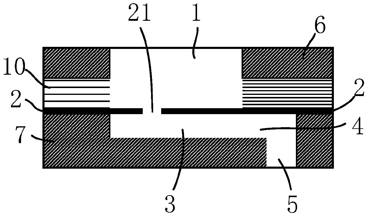
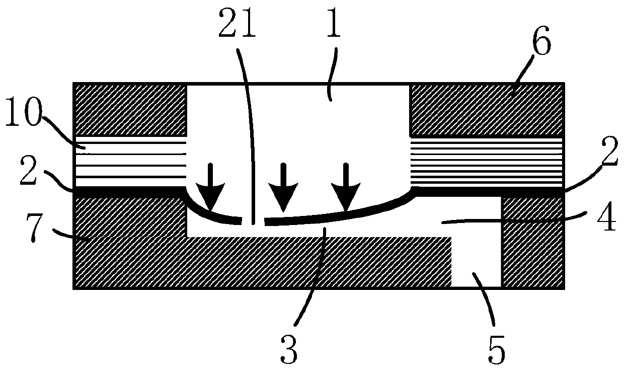
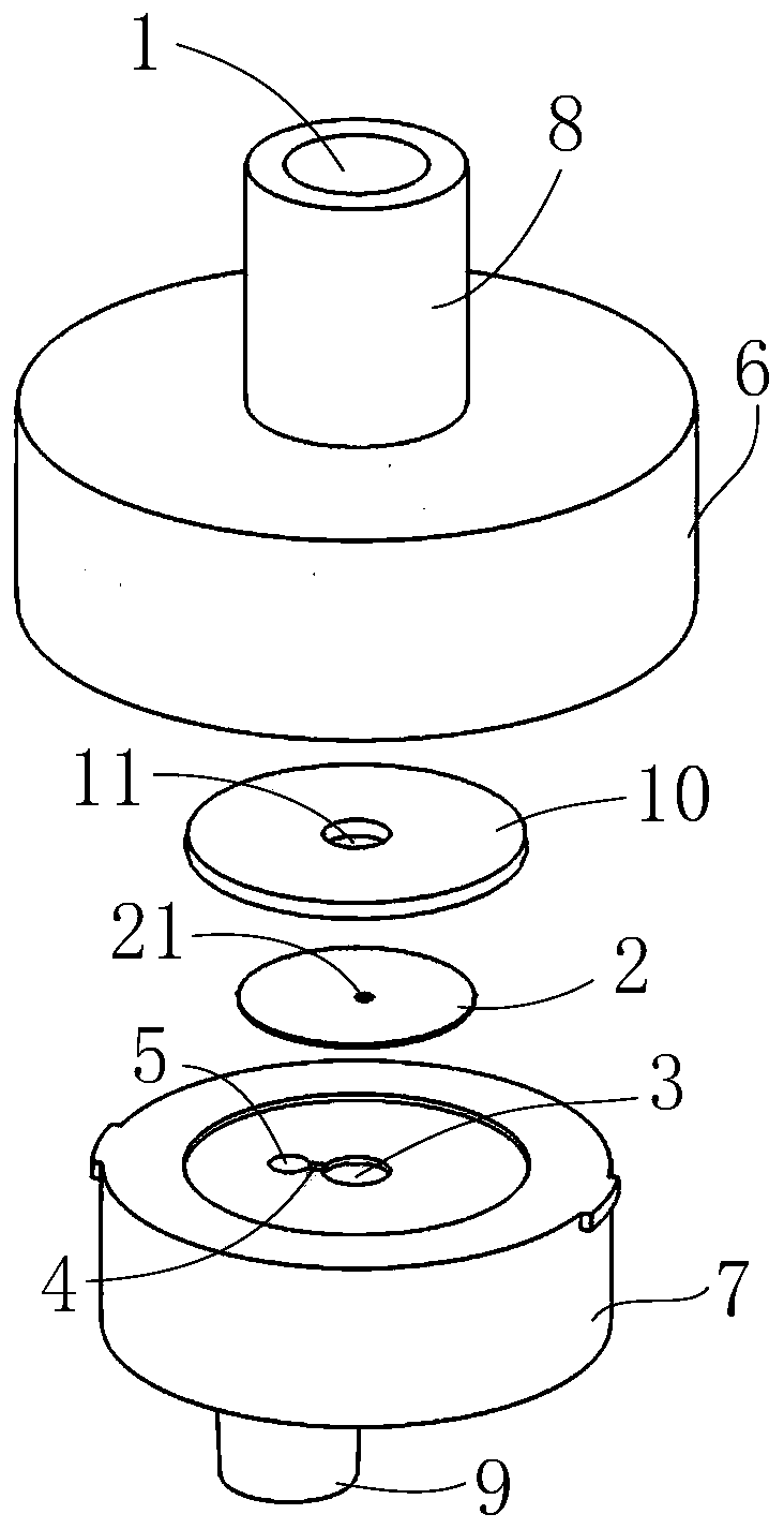
[0017] In order to realize that the conventional syringe can output accurate and stable sample flow rate under the hand-push drive, the present invention proposes a device for stabilizing the flow rate of the syringe. Such as figure 1 , the device is provided with a flow path capable of stabilizing the flow of sample liquid, and the flow path includes a liquid inlet channel 1 , a through hole 21 arranged on the elastic membrane 2 , a chamber 3 , a radial channel 4 and a liquid outlet channel 5 . Such as figure 2 , when the syringe is pushed by hand to drive the sample liquid, the elastic membrane 2 deforms into the chamber 3 under the pressure of the sample liquid, and gradually approaches the bottom of the chamber 3, squeezing the space of the chamber 3. During the gradual deformation of the elastic membrane 2, the through hole...


PUM


Abstract

The invention discloses a syringe flow stabilizing device. In order to output stable flow, an elastic membrane which can deform under the hydraulic pressure of a sample and a chamber which is matchedwith the elastic membrane in use are arranged in a sample flow path inside the device. When a syringe is pushed, the elastic membrane deforms towards the chamber under the hydraulic pressure of a sample to extrude the internal space of the chamber. As a through hole arranged in the elastic membrane gradually gets bigger, the space of the chamber gradually gets smaller. Thus, the intensity of pressure applied to the elastic membrane is always in direct proportion to the flow resistance in the flow path, and the whole flow path can maintain stable flow. With the syringe flow stabilizing device,an accurate and stable sample flow can be output when a syringe is pushed by a hand. The device has a compact structure, and is suitable for portable precise dispensing of samples.

Description

technical field [0001] The invention relates to a flow stabilizing device, in particular to a miniature flow stabilizing device used for a syringe. Background technique [0002] Medical syringes are currently the most commonly used sample injection distribution tools, and are widely used in medical quantitative drug delivery, instrument sample injection, experimental sample transfer and distribution, etc. At present, there are mainly two driving modes of syringes: mechanical driving and manual driving. Mechanical drive is to use motor control equipment such as precision medical syringe pumps to push the piston rod of the syringe to achieve precise flow distribution of the sample. This type of method has high precision, but has defects such as strong equipment dependence and high cost, and is not suitable for portable and fast applications. Hand drive is the most commonly used and easiest form of sample drive for syringes, but its stability in providing drive flow is seriou...

Claims


Application Information

Patent Timeline
IPC IPC(8): G05D7/01
Inventor 项楠倪中华
Owner SOUTHEAST UNIV
Why Eureka
Try Eureka