Manual cable bending machine

A bending machine and bending mechanism technology, applied in the direction of overhead line/cable equipment, etc., can solve the problems of damage to the outer skin of the power cable, inability to meet the power cable, high labor intensity, etc., to achieve high labor intensity and prevent the internal shielding layer. Breaking, overcoming the effect of irregular bending

Pending Publication Date: 2018-01-23
STATE GRID CORP OF CHINA +1
View PDF7 Cites 10 Cited by
  • Summary
  • Abstract
  • Description
  • Claims
  • Application Information

AI Technical Summary

Problems solved by technology

In the traditional bending of power cables, the operator often estimates the bending length and the radian of the curve in advance, and uses his hands and other parts of the body, or two or more people to forcefully bend the cable into a certain curvature, which is very laborious and inefficient. The cable section reaches 95-120mm 2 , the bending work must be completed with the cooperation of two or more people at the same time, and the bending time is longer, and when the cable cross section reaches 120mm 2 When it is more than that, it is extremely difficult for the operator to complete it manually. It is necessary to fix one end of the cable with a foreign object and then force the other end to complete the bending. This will cause certain difficulties in the construction and maintenance of the power cable and the process is not standardized. , and it is very easy to cause damage to the outer skin of the power cable, and the labor intensity is high and the efficiency is low, which cannot meet the needs of power cable construction

Method used


Image

  • Manual cable bending machine
  • Manual cable bending machine
  • Manual cable bending machine

Examples


Embodiment Construction

[0033] The present invention will be further described below in conjunction with the accompanying drawings and embodiments.

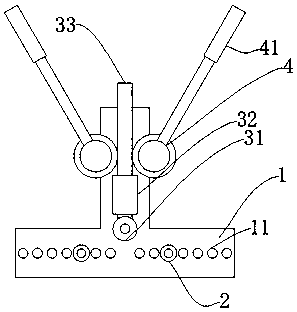
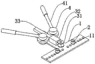
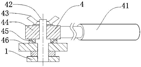
[0034] refer to Figure 1 to Figure 6 , Embodiment 1, this embodiment is a manual cable 5 bending machine, which includes a body 1, a bending mechanism, a feed mechanism 3 and a driving mechanism 4, the bending mechanism is placed on the body 1, and one end is connected to the body 1 Fixed connection; the feed mechanism 3 is placed on the body 1, on the side of the bending mechanism, the bottom surface of the feed mechanism 3 is fixed to the body 1, and the end is fixed to the bending mechanism; the driving mechanism 4 is placed on the body 1 On both sides of the feeding mechanism 3 , the bottom surface of the driving mechanism 4 is firmly connected with the body 1 , and the middle is in contact with the feeding mechanism 3 .

[0035] The body 1 is a T-shaped base, and the horizontal plate of the T-shaped base is provided with fourteen through holes 11...


PUM


Abstract

The invention relates to a manual cable bending machine. The manual cable bending machine is characterized by comprising a body, a bending mechanism, a feeding mechanism and driving mechanisms, wherein the bending mechanism is arranged on the body and is fixedly connected with the body, the feeding mechanism is arranged on the body and on a side surface of the bending mechanism, a bottom surface of the feeding mechanism is fixedly connected with the body, an end is fixedly connected with the bending mechanism, the driving mechanisms are arranged on the body and at two sides of the feeding mechanism, a bottom surface of each driving mechanism is fixedly connected with the body, and a middle part of each driving mechanism is in contact with the feeding mechanism. The application method comprises the steps of calculating minimum bending diameter of a cable, placing fixed rollers in through holes at appropriate positions of the body, fixedly connecting the fixed rollers, placing the cablein the bending mechanism, locking the driving mechanism, simultaneously rotating handles of the driving mechanisms by two hands, driving a gear to rotate by the driving assembly, driving a rack and apush plate to move by the gear, wherein the push plate moves relative to the two fixed roller so that the cable is bent and is plastically deformed to achieve cable bending.

Description

technical field [0001] The invention relates to power supply engineering equipment, in particular to a power cable construction tool, which is a manual cable bending machine. Background technique [0002] At present, in the construction of power cables, in order to realize the effective connection with power supply equipment such as overhead lines, switch cabinets and metering facilities, it is necessary to use external forces to bend the power cables into a certain arc, so that the direction of the power cables can be effectively changed. It is called power cable bending. With the acceleration of the industrialization of small towns and the continuous advancement of the electrification of new rural areas, power supply companies and power customers have higher and higher standards for the design, construction, and maintenance of power facilities, and the awareness of safe power supply and use has gradually increased. Power cables The use has gradually gained popularity. Wi...

Claims


Application Information

Patent Timeline
Patent Type & Authority Applications(China)
IPC IPC(8): H02G1/02
Inventor 唐晓峰刘加华姚士文王会星李郁石牛强郭威吴显舟邹刚于伟东王传宇王雨薇于永忠
Owner STATE GRID CORP OF CHINA
Why Eureka
Try Eureka