COB spotlight
A technology of heat dissipation lamp body and heat dissipation unit, which is applied in the direction of refractor, cooling/heating device of lighting device, gas/waterproof device, etc., can solve the problems of poor timeliness, complex structure, poor heat dissipation effect, etc., to increase the heat dissipation effect , The effect of obvious heat dissipation and simple structure
- Summary
- Abstract
- Description
- Claims
- Application Information
AI Technical Summary
Problems solved by technology
Method used
Image

Examples
Embodiment 1
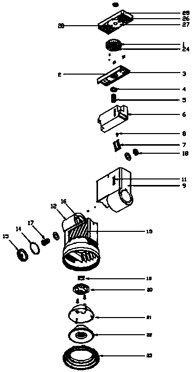
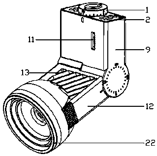
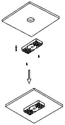
[0030] Such as figure 1 , 2 , 4-8, the COB spotlight includes a pad shaft 1, a drive unit, a heat dissipation unit, a luminous body unit, and a light-transmitting component. The drive unit connected to the pad shaft 1 rotates at a suitable angle to meet different lighting requirements. When installing the COB spotlight, it is necessary to install the ceiling device. When installing, the ceiling device can be carried for the desired angle. Adjustment, the pad shaft is provided with a card slot 24, and the upper surface of the pad shaft is connected with the ceiling device. In the groove 27, the protrusion 28 on the buckle groove 27 is matched with the draw-in groove 24 on the pad shaft to make the connection between the pad shaft and the ceiling device more stable. , you only need to use screws to stabilize the ceiling. The installation is relatively simple and easy to use. The ceiling installation structure is as follows: image 3 As shown, the structure of the connection b...
Embodiment 2
[0036] Such as figure 1 , 2 , 5-8, the COB spotlight includes a pad shaft 1, a drive unit, a heat dissipation unit, a luminous body unit, and a light-transmitting component. The drive unit connected to the pad shaft 1 rotates at a suitable angle to meet different lighting requirements. When installing the COB spotlight, install and fix the COB spotlight through the pad shaft 1 and the guide rail head, and install the guide rail head at the same size as the guide rail head. In the matching guide rail, the whole device can be moved along with the guide rail. The installation structure of the guide rail is as follows: Figure 4 As shown, the structure of the connection between the pad shaft 1 and the ceiling block is as follows Figure 8 As shown, at the same time, a groove matching the size of the pad shaft 1 is opened on the ceiling block, and the drive unit includes an electric box cover 2, a meson 4, a hollow screw 5, a driver 6, a drive shrapnel 7, and a drive box 9 , the...
PUM
 Abstract
Description
Claims
Application Information
 - R&D Engineer
- R&D Manager
- IP Professional
- Industry Leading Data Capabilities
- Powerful AI technology
- Patent DNA Extraction
Browse by: Latest US Patents, China's latest patents, Technical Efficacy Thesaurus, Application Domain, Technology Topic.
© 2024 PatSnap. All rights reserved.Legal|Privacy policy|Modern Slavery Act Transparency Statement|Sitemap