A position and attitude adjustment method for a position and attitude adjustment mechanism and antenna test

A technology of adjusting mechanism and adjusting method, which is applied in the direction of antenna radiation pattern and feedback control, can solve the problems of poor generalization, long cycle, high cost, etc., and achieve simple and convenient adjustment method, wide application range and strong versatility Effect

Active Publication Date: 2020-05-29
BEIJING INST OF RADIO METROLOGY & MEASUREMENT
View PDF11 Cites 0 Cited by
  • Summary
  • Abstract
  • Description
  • Claims
  • Application Information

AI Technical Summary

Problems solved by technology

[0003] In the traditional installation and adjustment method, the rotation accuracy of each axis of the turntable is guaranteed by the manufacturer. The tooling is installed on the spinning disk, and the tooling and the notch of the spinning disk are used for positioning, and then the laser source is installed on the tooling and the laser point is used to directly align the antenna position. The disadvantage of the method is that the coaxiality of the

Method used


Image

  • A position and attitude adjustment method for a position and attitude adjustment mechanism and antenna test
  • A position and attitude adjustment method for a position and attitude adjustment mechanism and antenna test
  • A position and attitude adjustment method for a position and attitude adjustment mechanism and antenna test

Examples


Embodiment Construction

[0026] In order to make the purpose, technical solution and advantages of the present application clearer, the technical solution of the present application will be clearly and completely described below in conjunction with specific embodiments of the present application and corresponding drawings. Apparently, the described embodiments are only some of the embodiments of the present application, rather than all the embodiments. Based on the embodiments in this application, all other embodiments obtained by persons of ordinary skill in the art without making creative efforts belong to the scope of protection of this application.

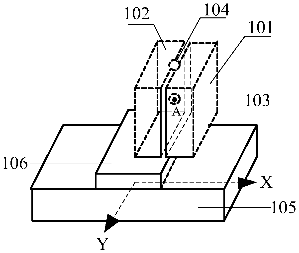
[0027] figure 1 It is a schematic diagram of the position and attitude adjustment mechanism.

[0028] The position and posture adjustment mechanism includes a rotating component 101 , a translation component 102 , a first connection structure 103 , a second connection structure 104 , an X-axis translation device 105 and a Y-axis translation device 10...


PUM


Abstract

The application discloses a position and attitude adjusting mechanism and a position and attitude adjusting method for antenna tests, aiming at addressing the overlapping precision between the centeraxis of a self-spinning disk of a turntable and the center axis of an antenna on a reflection surface. The position and attitude adjusting mechanism includes a rotation part, a translation part, a first connection structure, a second connection structure, an X-axis translation apparatus and a Y-axis translation apparatus. The method includes the following steps: adjusting the X-axis and the Y-axisof a laser source to perform rotation and translation, such that laser light leaves smallest track which serves as a reference point; adjusting the installation surface of an antenna such that the reference point falls to the center pf the antenna; installing a reflector, such that when the self-spinning disk rotates, laser light is reflected by the reflector to the self-spinning disk so as to form a reflection track point; and adjusting the antenna to rotate in the X-axis and Y-axis directions, such that when the self-spinning disk rotates, the reflection leaves smallest track. According tothe invention, the mechanism has the characteristics of simple structure, small size, simplified installation, easy use, and excellent expandability. The method has the characteristics of easiness, excellent universality and wide application.

Description

technical field [0001] The invention belongs to the field of mechanical design, and in particular relates to a position and attitude adjustment mechanism and an adjustment method. Background technique [0002] During the test of the missile radome, the test turntable is usually used. During the test, the central axis of the spin plate of the turntable is required to have a high degree of coincidence with the central axis of the reflector antenna in the distance. [0003] In the traditional installation and adjustment method, the rotation accuracy of each axis of the turntable is guaranteed by the manufacturer. The tooling is installed on the spinning disk, and the tooling and the notch of the spinning disk are used for positioning, and then the laser source is installed on the tooling and the laser point is used to directly align the antenna position. The disadvantage of the method is that the coaxiality of the laser source and the spin axis of the turntable cannot be guaran...

Claims


Application Information

Patent Timeline
IPC IPC(8): G01R29/10G05D3/12
Inventor 王鲲飞吴翔何鑫
Owner BEIJING INST OF RADIO METROLOGY & MEASUREMENT
Why Eureka
Try Eureka