Scanning device

A technology for scanning devices and scanners, applied in image communication, electrical components, etc., can solve the problems of bulky scanning devices and achieve the effect of reducing volume and shortening length

Active Publication Date: 2018-01-26
AVISION
View PDF2 Cites 5 Cited by
  • Summary
  • Abstract
  • Description
  • Claims
  • Application Information

AI Technical Summary

Problems solved by technology

[0005] Traditionally, in order to integrate the flatbed scanner 12 and the automatic document feeder 11 to jointly use the image capture module 121, many components must be used in the structure of the flatbed scanner 12, and the flatbed scanner 12 must additionally add The first transparent substrate and the bonding part are arranged in intervals, resulting in too large volume of the scanning device

Method used


Image

  • Scanning device
  • Scanning device
  • Scanning device

Examples


Embodiment Construction

[0041] The present invention will be described in detail below in conjunction with the accompanying drawings and embodiments.

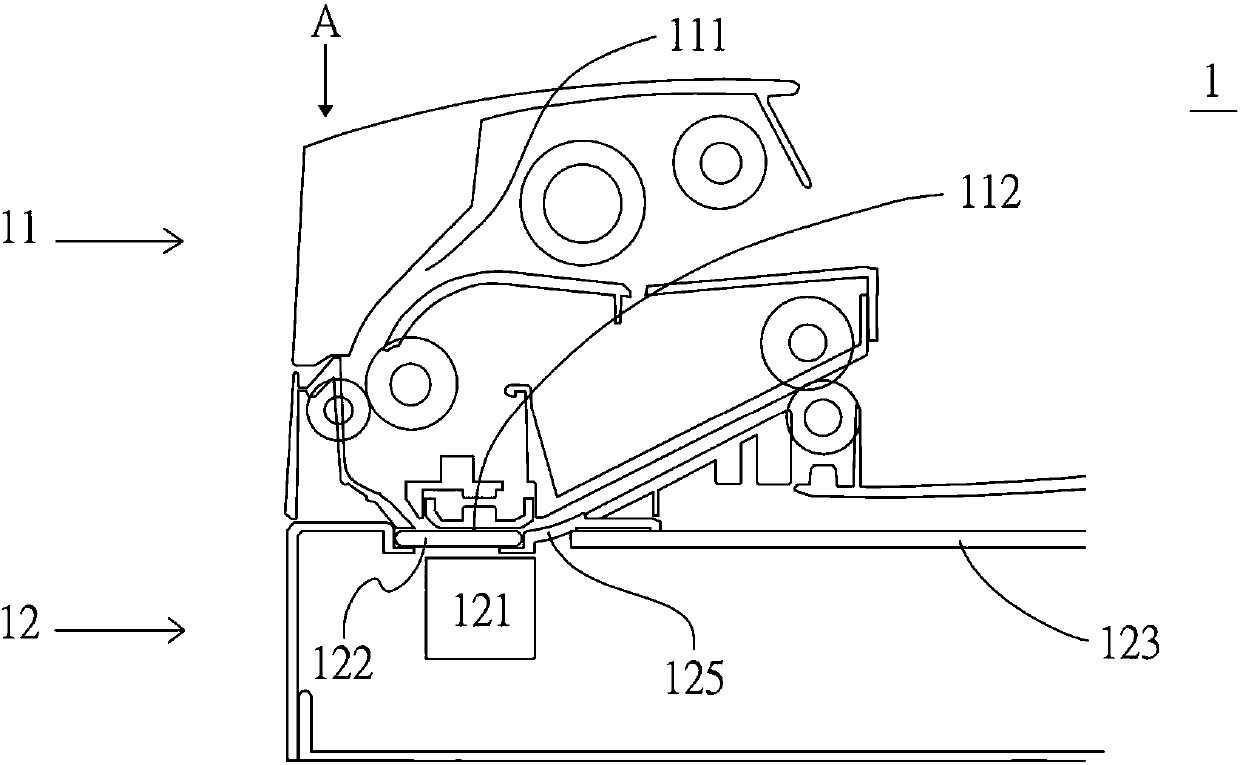
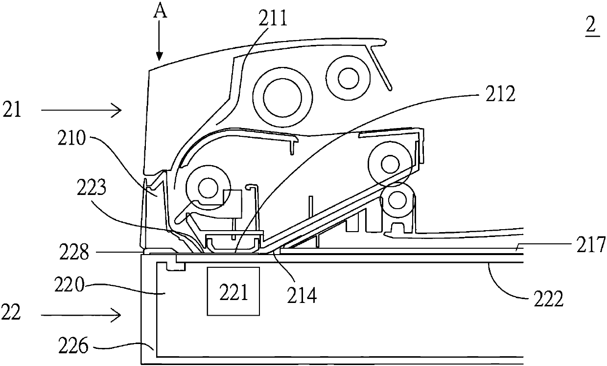
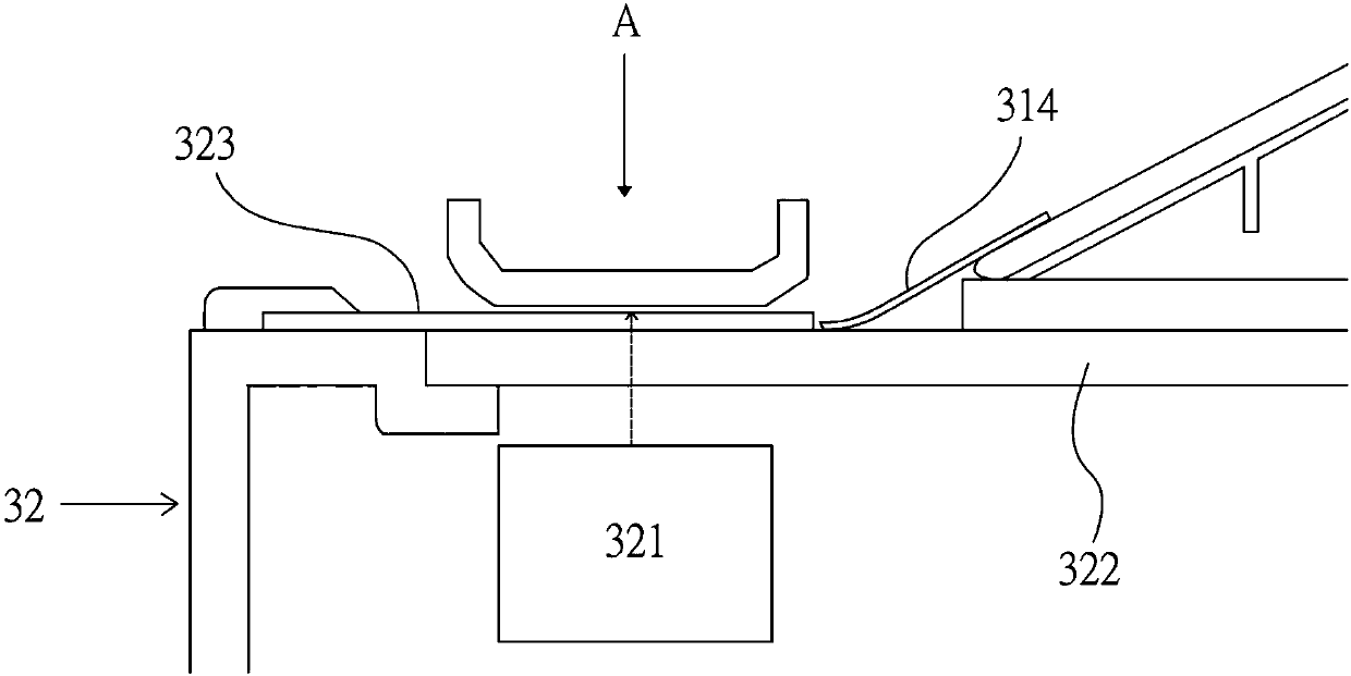
[0042] see figure 2 , figure 2 It is a schematic structural diagram of the scanning device of the present invention. The present invention provides a scanning device 2, which can perform flat-bed and automatic paper-feeding image capture operations on paper. The scanning device 2 includes: a flatbed scanner 22 and an automatic document feeder 21 . The flatbed scanner 22 includes a first body 220 , a transparent substrate 222 , a first film 223 and an image capture module 221 . Wherein, the transparent substrate 222 is disposed on the upper surface of the first body 220 , and the first film 223 is close to the first end A of the upper surface of the transparent substrate 222 . In addition, the image capture module 221 is disposed at the first end A of the lower surface of the transparent substrate 222 .

[0043] Furthermore, the automatic docume...


PUM


Abstract

The disclosure provides a scanning device including a flatbed scanner and an ADF. The flatbed scanner includes a first body, a transparent substrate disposed on top surface of the first body, a firstfilm disposed on top surface of the transparent substrate, and an image capturing module disposed under bottom surface of the transparent substrate. The ADF includes a second body, a backplane disposed at bottom of the second body for covering top surface of the flatbed scanner, a paper passage disposed inside the ADF, and a second film. An open portion is configured in the paper passage corresponding to top surface of the transparent substrate, and results communication between the paper passage and top surface of the transparent substrate. The second film is disposed at paper entrance of theopen portion. Wherein, the first film and the second film are not overlap on top surface of the transparent substrate.

Description

technical field [0001] The present invention relates to a scanning device, in particular to a scanning device which has the functions of platform scanning and feed-in scanning. Background technique [0002] The traditional scanning device is composed of a flatbed scanner and an automatic document feeder. Users can use the flatbed scanner to scan documents in a flat scanning manner, or use the automatic document feeder to scan multiple documents. [0003] figure 1 Shown is a schematic structural view of a prior art scanning device. Please refer to figure 1 , in the prior art scanning device 1 , the flatbed scanner 12 and the automatic document feeder 11 share the image capturing module 121 . Based on the shared factors of the image capture module 121 , the image capture module 121 is disposed inside the first end A of the flatbed scanner 12 . Correspondingly, the automatic document feeder 11 is also arranged at the first end A above the flatbed scanner 12 . In addition, ...

Claims


Application Information

Patent Timeline
Patent Type & Authority Applications(China)
IPC IPC(8): H04N1/10H04N1/12
CPCH04N1/00588H04N1/1061H04N2201/0081
Inventor 盛少澜陈继耀
Owner AVISION
Why Eureka
Try Eureka