Seatbelt retractor

A technology for seat belts and retractors, applied in the direction of belt tensioners, etc.

Active Publication Date: 2018-01-26
AUTOLIV DEV AB
View PDF7 Cites 4 Cited by
  • Summary
  • Abstract
  • Description
  • Claims
  • Application Information

AI Technical Summary

Problems solved by technology

Moreover, when there is a possibility of a collision, the seat belt is wound by a certain amount to slightly restrain the driver and occupants.

Method used


Image

  • Seatbelt retractor
  • Seatbelt retractor
  • Seatbelt retractor

Examples


Embodiment Construction

[0048] Hereinafter, a retractor for a seat belt according to an embodiment of the present invention will be described in detail with reference to the drawings.

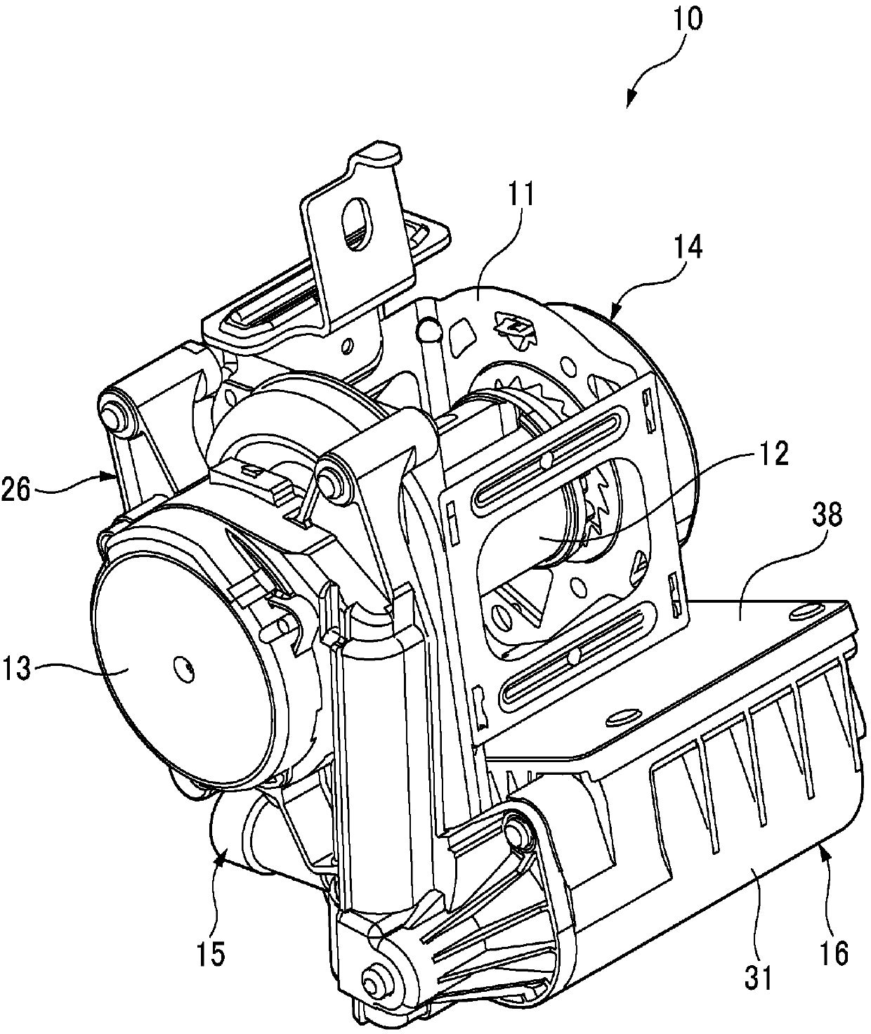
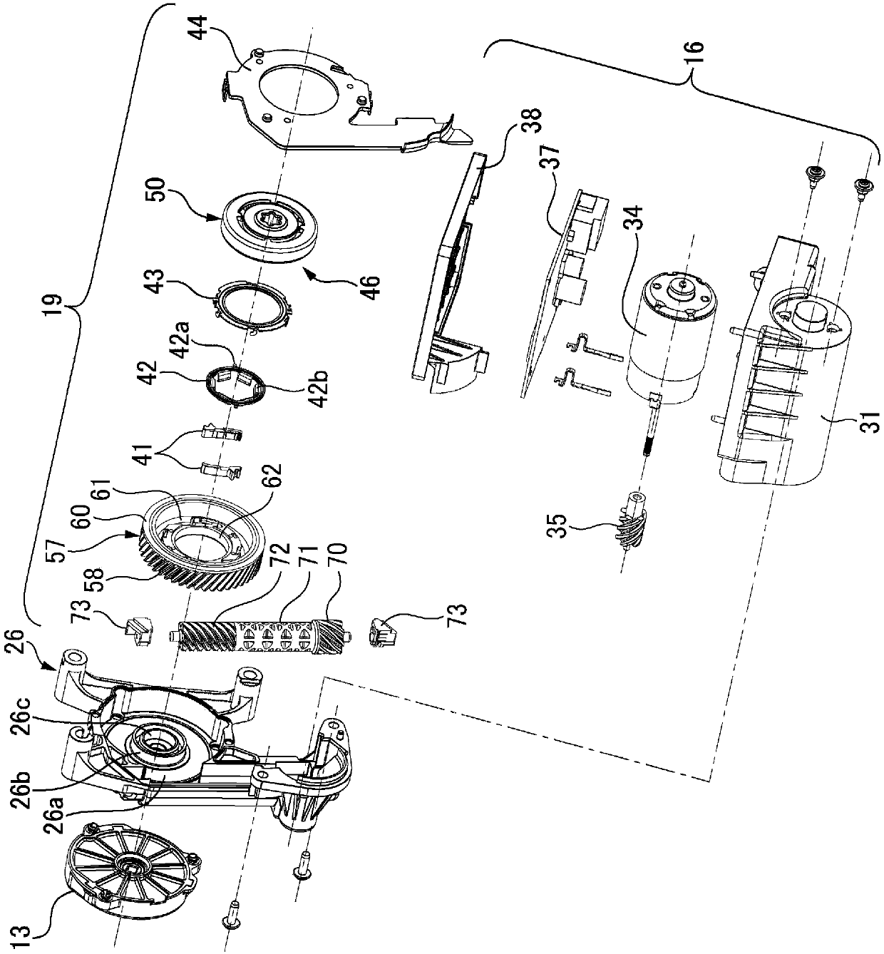
[0049] Such as figure 1 and figure 2 As shown, the seat belt retractor 10 according to this embodiment has: a mandrel 12 not shown in the figure for winding the seat belt; a coil spring device 13 for urging the mandrel 12 in the winding direction of the seat belt; The locking mechanism 14 that locks the pull-out action of the seat belt based on the acceleration detected by the acceleration sensor not shown in the figure; the motor 34 that is an electric actuator that generates power to rotate the spindle 12; A pretensioner 15 for other power; a power transmission mechanism 19 capable of transmitting the power from the motor 34 to the spindle 12 .

[0050] Both ends of the mandrel 12 are rotatably supported by the retractor frame 11 . In addition, a not-shown torsion bar constituting an energy absorbing mechanism ...


PUM


Abstract

This power transmission mechanism (19) for transmitting power from a motor (34) to a spindle (12) is provided with: a clutch housing (50); a pawl (41) that is able to engage with the clutch housing (50); a gear wheel (57) that holds the pawl (41) and rotates according to the rotation of the motor (34); an outer gear cover (26); and a friction ring (42) engaging with the pawl (41) and held on the outer gear cover (26) due to frictional force. The friction ring (42) is provided with: a protrusion part (42a) that engages with an engagement groove (41b) of the pawl (41); and a plurality of contactpieces (42b) that come into contact with the outer peripheral surface of a small diameter ring part (26c) of the outer gear cover (26) and press against the small diameter ring part (26c) toward theinside in the radial direction. Consequently, assembly of the friction ring onto the outer gear cover can be facilitated.

Description

technical field [0001] The present invention relates to a seat belt retractor, and more particularly to a seat belt retractor capable of winding up a slack seat belt by rotating a spindle using an electric actuator. Background technique [0002] Conventional seat belt retractors use sensors to detect sudden deceleration of the vehicle, and use motors to rotate the mandrel in the winding direction. Furthermore, when there is a possibility of a collision, the seat belt is wound by a certain amount to lightly restrain the driver and occupants. In addition, at the time of a collision, the explosive type pretensioner is activated to forcibly wind the seat belt, thereby reliably protecting the occupants. [0003] In addition, the seat belt retractor is equipped with a clutch mechanism on the power transmission mechanism that transmits the power from the motor to the spindle, which can transmit and cut off the power from the motor to the spindle, so as to prevent damage caused by ...

Claims


Application Information

Patent Timeline
Patent Type & Authority Applications(China)
IPC IPC(8): B60R22/46
Inventor 前村英二安德烈亚斯·卢赫特帕特里克·聚尔奥绿川幸则
Owner AUTOLIV DEV AB
Why Eureka
Try Eureka