
Water flow analysis

A water main and a part of the technology, applied in the field of knowing the water flow in the place, can solve the problems of impractical and uneconomical water supply systems

Active Publication Date: 2018-01-26
LEAKBOT LTD
View PDF11 Cites 1 Cited by
  • Summary
  • Abstract
  • Description
  • Claims
  • Application Information

AI Technical Summary

Problems solved by technology

Even though leaks are in principle found using acoustic techniques, this is not practical or economical in real-world situations due to the size of the water supply system and the need to perform an exhaustive search
Additionally, new leaks can occur at any time

Method used


Image

  • Water flow analysis
  • Water flow analysis
  • Water flow analysis

Examples


Embodiment Construction

[0086] refer to figure 1 , shows a schematic cross-sectional view of a location 100 including a facility 120 associated with a site 102 according to aspects of the invention. In the position shown, the venue 102 is a family residence, and specifically a house. It will be appreciated that in other embodiments the establishment may take other forms, for example it may be a commercial establishment and may be any establishment with a water supply from a local water main. exist figure 1 In , the water main 110 forms part of the water distribution network and is buried approximately 1 m below the road surface 112 . A sleeve 114 extends from the upper portion of the water main and is in fluid communication with a first portion 116 of the service pipe at a depth typically of approximately 0.75m, and it extends from the water main 110 below the walkway 118, typically for a distance of several meters.

[0087] An outer shut-off tap or metering chamber 122 is disposed below the walkw...


PUM


Abstract

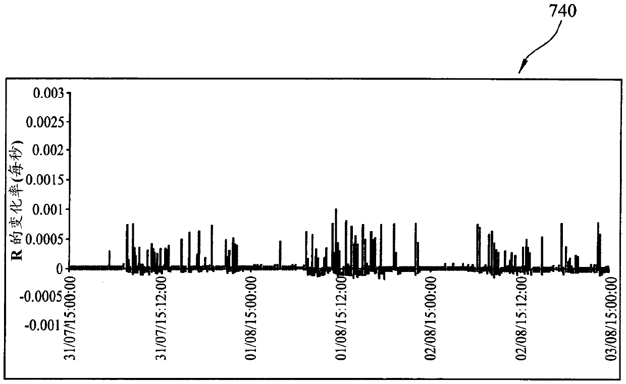
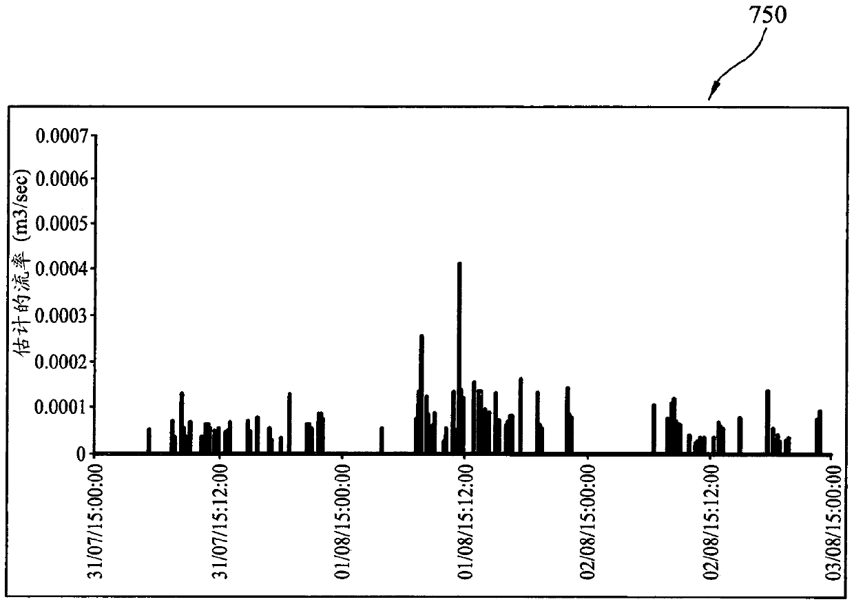
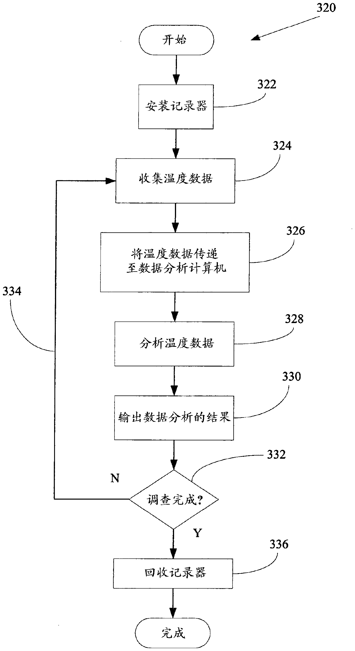
The invention relates to water flow analysis. According to the invention, a location (100) is including an installation (120) associated with a site (102). At the site (102) is a house. A water main (110) forms part of a water distribution network and is buried approximately 1m below the surface (112) of a road. A ferrule (114) extends from an upper part of the water main pipe and is in fluid communication with a first portion (116) of a service pipe at depth of typically approximately 0.75m and which extends from the water main (110) to underneath a pavement (118). An outside stop-tap or meter chamber (122) is provided below pavement (118) and includes a pilotable cover (124), which can be opened to provide access to the interior of the chamber (122). A first connector (126) is provided on an upstream side of the chamber and a second connector (128) is provided on a downstream side of the chamber. A stop-tap or stop-tap and meter assembly (130) is provided within the chamber and in fluidic communication with the first and second connectors. An insulating member (134), for example in the form of a piece of polystyrene, extends across the interior of the chamber (122) and acts to insulate the lower part of the chamber from the environment above. A temperature logging device (160) is located on the insulating member (134) and includes a first temperature sensor (162). Optionallythe temperature logging device may also include a second temperature sensor (164).The temperature of a part of a water supply system between a water main (110) and a site is recorded as a function oftime. The recorded temperature as a function of time is analyzed to determine a property indicative of the water consumption at the site.

Description

technical field [0001] The present invention relates to liquid flow analysis, and in particular to methods, devices, apparatus and systems that can be used to understand water flow within a venue. Background technique [0002] There are many utilities that are commonly provided to homes and businesses. Such utilities include gas, electricity and water. Metering can be used at various locations in order to determine the amount of utility consumed at that location. While separate electricity and gas meters are fairly common for many establishments, separate water meters are less common. Leakage or escape of gas from supply systems or appliances within the premises is detectable due to odor. Electricity is not a fluid, and therefore in principle cannot leak or dissipate. [0003] Because many water systems are buried underground, many water leaks are not easy to spot or detect. Some leaks or escapes of water are clearly detectable, including leaks where the effect of the l...

Claims


Application Information

Patent Timeline
Patent Type & Authority Applications(China)
IPC IPC(8): G01M3/28
CPCG01M3/2807F17D5/02G01M3/002G01F1/68G01M3/26
Inventor S.图姆斯S.特罗
Owner LEAKBOT LTD
Learn More