Cutting equipment of novel rectangular plate large-area peeling device

A cutting equipment, rectangular technology, applied in the direction of grinding/polishing equipment, metal processing equipment, machine tools suitable for grinding workpiece planes, etc., can solve the problems of inconvenient control, complex structure, and inability to clean rectangular plates, etc., to achieve Improve practicality and facilitate cleaning

Inactive Publication Date: 2018-01-30
蔡涛涛
1 Cites 20 Cited by

AI-Extracted Technical Summary

Problems solved by technology

[0002] The recycling and reprocessing of rectangular plates can not only save wood resources but also save production and processing costs. The first step after recycling the rectangular plates is to remove the remaining paint or other attachments on the two large surfaces of the rectangular plates. The skin on the two large surfaces of the rectangular plate is removed, but most of the cutting equipment used by the traditional peeling device to control the peeling is complex in structure and inconvenient to control and use. It is impossible to cut the rectangular plate cleanly and the surface of the rectangular plate cannot be preliminary Grinding, such as the patent application publication number 201520619567.7, discloses a new type of ...

Method used

The cutting scraper 26 that the present invention is provided with on the outer side of cutting ferrule 16 can cut rectangular plate material cleanly, and grinding ferrule 10 can carry out preliminary grinding to the surface of rectangular plate material, and axle connecting p...

Abstract

The invention discloses cutting equipment of a novel rectangular plate large-area peeling device. The cutting equipment comprises a base. A waste scrap tank is arranged on the upper side of the base,two support plates are arranged on the side, which is close to the waste scrap tank, of the base and are symmetrically distributed, more than four fixing holes are symmetrically formed in the side, which is close to the support plates, of the base, more than four support rods are arranged on a side of the base and are equidistantly symmetrically distributed, a first annular fixing boss is connected with one end of each of the two corresponding support rods, and an output shaft of a first servo motor is connected with an end of a cutting rotary shaft by couplings. The cutting equipment has theadvantages that rectangular plates can be thoroughly cut by cutting scraper knives arranged on the outer sides of cutting collars, the surfaces of the rectangular plates can be preliminarily polishedby polishing collars, the cutting distances can be adjusted by shaft connecting plates and adjusting wheels according to the heights of the rectangular plates, accordingly, the practicality of the cutting equipment can be greatly improved, and the waste scrap tank can bring convenience for cleaning waste scraps.

Application Domain

Technology Topic

Image

  • Cutting equipment of novel rectangular plate large-area peeling device
  • Cutting equipment of novel rectangular plate large-area peeling device
  • Cutting equipment of novel rectangular plate large-area peeling device

Examples

  • Experimental program(1)

Example Embodiment

[0022] The following will clearly and completely describe the technical solutions in the embodiments of the present invention with reference to the accompanying drawings in the embodiments of the present invention. Obviously, the described embodiments are only some, not all, embodiments of the present invention. Based on the embodiments of the present invention, all other embodiments obtained by persons of ordinary skill in the art without making creative efforts belong to the protection scope of the present invention.
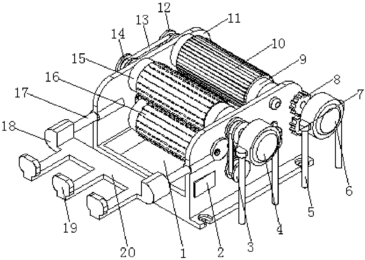
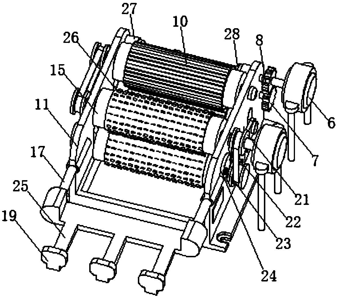
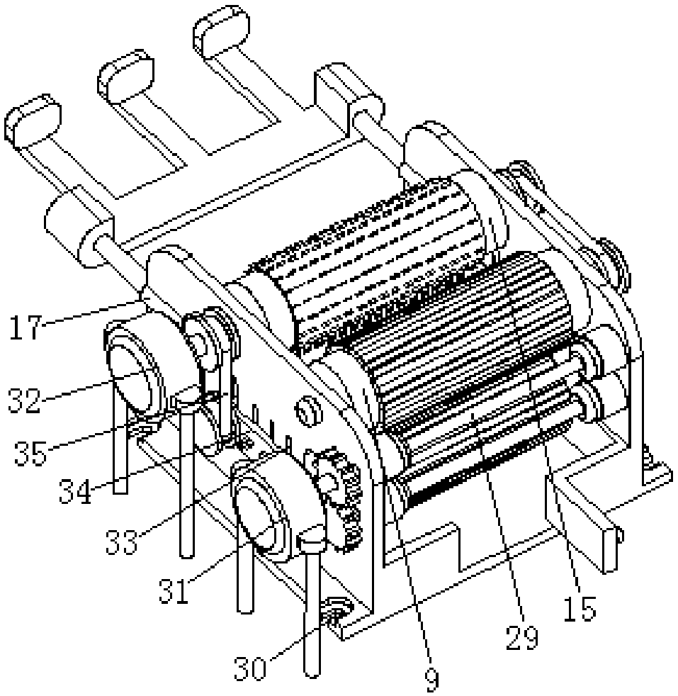
[0023] see Figure 1-5, the present invention provides a technical solution: a new type of cutting equipment for a large-face peeling device for rectangular plates, including a base 1, and a waste box 38 is provided on the upper side of the base 1 to store waste and facilitate cleaning. One side of 38 is connected with side door 36 by hinge, and side door 36 is provided with handle 37 away from the side of waste container 38, and base 1 is provided with two groups of support plates 11 of symmetrical distribution near the side of waste container 38, and base 1 The side close to the support plate 11 is provided with more than four sets of fixing holes 30 symmetrically distributed for fixing the base 1, and one side of the base 1 is provided with more than four sets of support rods 5 equidistant and symmetrically distributed, wherein two sets of support rods One end of the 5 is connected with a first annular fixed boss 32, and one end of the other two groups of support rods 5 is connected with a second annular fixed boss 31, and the inner middle position of the first annular fixed boss 32 is provided with a first servo motor 4, The side of the support plate 11 close to the first servo motor 4 is connected with two groups of symmetrically distributed electric telescopic rods 17, and the end of the electric telescopic rods 17 away from the support plate 11 is connected with a connecting boss 18, and the connecting bosses 18 are connected by placing The plate 20 is connected, and the side of the placing plate 20 away from the connecting boss 18 is connected with more than three groups of connecting ribs 25 equidistantly distributed, and the end of the connecting rib 25 away from the placing plate 20 is connected with a pressure plate 19, and the output terminal of the control switch 2 Connect the input end of the electric telescopic rod 17, the output shaft of the first servo motor 4 is connected with an end of the cutting shaft 41 through a shaft coupling, and the middle position of the cutting shaft 41 is provided with two groups of cutting drums 15 symmetrically distributed, and the cutting drum 15 Cutting collars 16 are provided on the outer sides, and the side of the cutting collars 16 away from the cutting drum 15 is provided with uniformly distributed cutting scrapers 26 for cutting rectangular plates. Two sets of distributed first V-pulley 3 and fourth V-pulley 21 are connected through the second V-belt 35 between the first V-pulley 3 and the fourth V-pulley 21, and the support plate 11 is close to the second V-shaped pulley. One side of the belt 35 is provided with a disk 24, and the eccentric position of the disk 24 is connected with the support plate 11 through a set bolt 23, and the side of the disk 24 near the second V-shaped belt 35 is provided with an adjustment wheel 22 for adjusting The tightness of the second V-shaped belt 35, the other end of the cutting shaft 41 runs through the support plate 11 and is connected with the support plate 11 through a bearing. The side of the support plate 11 near the cutting shaft 41 is connected with a grinding shaft 42 through a bearing. The two ends of the waste container 38 are respectively connected with the two ends of the grinding shaft 42 close to the waste container 38 through the shaft connection plate 34, and the side of the support plate 11 near the shaft connection plate 34 is provided with more than three groups of connection grooves distributed equidistantly 33, the inner middle position of the connecting groove 33 is provided with a hexagonal bolt, the hexagonal bolt is connected with the shaft connecting plate 34 through the connecting groove 33, and the middle position of the grinding rotating shaft 42 is provided with two groups of symmetrically distributed grinding drums 9, and the outer side of the grinding drum 9 is provided with There are several grinding ferrules 10 equidistantly distributed, the end of the grinding shaft 42 away from the first servo motor 4 is provided with two sets of second V-belt pulleys 12 and the sixth V-pulley 40 symmetrically distributed, and the cutting shaft 41 is close to the second V-pulley. pulley 12 and one end of the sixth V-belt pulley 40 are respectively provided with the third V-belt pulley 14 and the fifth V-belt pulley 39, the second V-belt pulley 12 is connected with the third V-belt pulley 14 through the first V-shaped belt 13, and the third V-belt pulley 14 Six V-belt pulleys 40 are connected with the fifth V-belt pulley 39 through the third V-shaped belt 44, and the inner middle position of the second annular fixed boss 31 is provided with a second servo motor 6, and the output shaft of the second servo motor 6 is connected through the joint The shaft device is connected with one end of the transfer shaft 43, the other end of the transfer shaft 43 runs through the support plate 11 and is connected with the support plate 11 through a bearing, and the end of the transfer shaft 43 near the support plate 11 is provided with two groups of first gears 7 and 7 which are symmetrically distributed. The second gear 8, the first gear 7 and the second gear 8 gear meshing, the middle position of the transfer shaft 43 is provided with two groups of transmission wheels 28 symmetrically distributed, the transmission wheels 28 are connected by a connecting shaft 29, and the telescopic transmission wheels 28 Rubber ferrules 27 are provided on the outer sides of the support plate 11 for pulling out and conveying the rectangular plate. A control switch 2 is provided on one side of the support plate 11, and the output terminals of the control switch 2 are electrically connected to the first servo motor 4 and the second servo motor respectively. 6 inputs.
[0024] The mode that the control switch 2 controls the first servo motor 4, the second servo motor 6 and the electric telescopic rod 17 adopts the prior art.
[0025] When in use: put the rectangular plate on the upper side of the placement plate 20, and then control the opening of the electric telescopic rod 17 through the control switch 2, the electric telescopic rod 17 telescopically pushes the connected connecting boss 18 to move, and the moving of the connecting boss 18 drives the connected pressing plate 19 Push the rectangular plate to move between the two groups of cutting rollers 15. At this time, the first servo motor 4 and the second servo motor 6 are turned on in turn through the control switch 2, and the output shaft of the first servo motor 4 rotates to drive the connected cutting shaft 41 to rotate. , the cutting shaft 41 rotates to drive the first V-belt pulley 3 to rotate, and the first V-belt pulley 3 drives the fourth V-belt pulley 21 connected by the second V-shaped belt 35 to rotate, thereby driving the two groups of cutting drums 15 arranged in the middle to rotate Two groups of cutting drums 15 outside the two groups of cutting drums 15 cut the surface of the rectangular plate, the second V-belt pulley 12 is connected with the third V-belt pulley 14 through the first V-belt 13, and the fifth V-belt pulley 39 It is connected with the sixth V-belt wheel 40 through the third V-belt 44, thereby driving two groups of grinding rollers 9 to rotate, and the rotation of the two groups of grinding rollers 9 drives the grinding ring 10 provided on the outside to grind the rectangular plate, and after grinding, pass The rotation of the output shaft of the second servo motor 6 drives the connected transfer shaft 43 to rotate, and the rotation of the transfer shaft 43 drives the first gear 7 and the second gear 8 to engage and drive, thereby driving the connected transmission wheel 28 to pull out the rectangular plate. When the height is different, adjust the distance between the two groups of cutting rotating shafts 41 and the distance between the two groups of grinding rotating shafts 42 through the shaft connecting plate 34, and then fix the position of the shaft connecting plate 34 by the set bolt 23.
[0026] In the present invention, the cutting scraper 26 provided on the outside of the cutting ferrule 16 can cut the rectangular plate cleanly, the grinding ferrule 10 can initially polish the surface of the rectangular plate, and the shaft connecting plate 34 and the adjusting wheel 22 can be adjusted according to the height of the rectangular plate. The adjustment of the cutting distance greatly improves the practicability of the cutting equipment, and the waste chip box 38 facilitates the cleaning of waste chips.
[0027] Although the embodiments of the present invention have been shown and described, those skilled in the art can understand that various changes, modifications and substitutions can be made to these embodiments without departing from the principle and spirit of the present invention. and modifications, the scope of the invention is defined by the appended claims and their equivalents.

PUM

no PUM

Description & Claims & Application Information

We can also present the details of the Description, Claims and Application information to help users get a comprehensive understanding of the technical details of the patent, such as background art, summary of invention, brief description of drawings, description of embodiments, and other original content. On the other hand, users can also determine the specific scope of protection of the technology through the list of claims; as well as understand the changes in the life cycle of the technology with the presentation of the patent timeline. Login to view more.

Similar technology patents

Optical device

Owner:SUMITOMO ELECTRIC IND LTD

On-line training management system and method based on process tracking

InactiveCN103729701AImprove practicalityEasy to operateResourcesIntegrated databaseOnline learning
Owner:上海睿剑信息科技有限公司

Classification and recommendation of technical efficacy words

  • Easy to clean
  • Improve practicality

Cleaning Tool for Attachment Surfaces

InactiveUS20100000040A1Facilitate selective applicationEasy to cleanBoard cleaning devicesCarpet cleanersEngineeringMedical treatment
Owner:RETRACTABLE TECH INC
Why Eureka
Try Eureka