Photo printer
A technology of printers and photos, applied in typewriters, printing devices, printing, etc., can solve the problems of printing quality degradation, small friction between the pickup roller and paper, transmission, etc., and achieve the effect of improving printing quality, simple structure, and shrinking volume
- Summary
- Abstract
- Description
- Claims
- Application Information
AI Technical Summary
Problems solved by technology
Method used
Image

Examples
Embodiment Construction
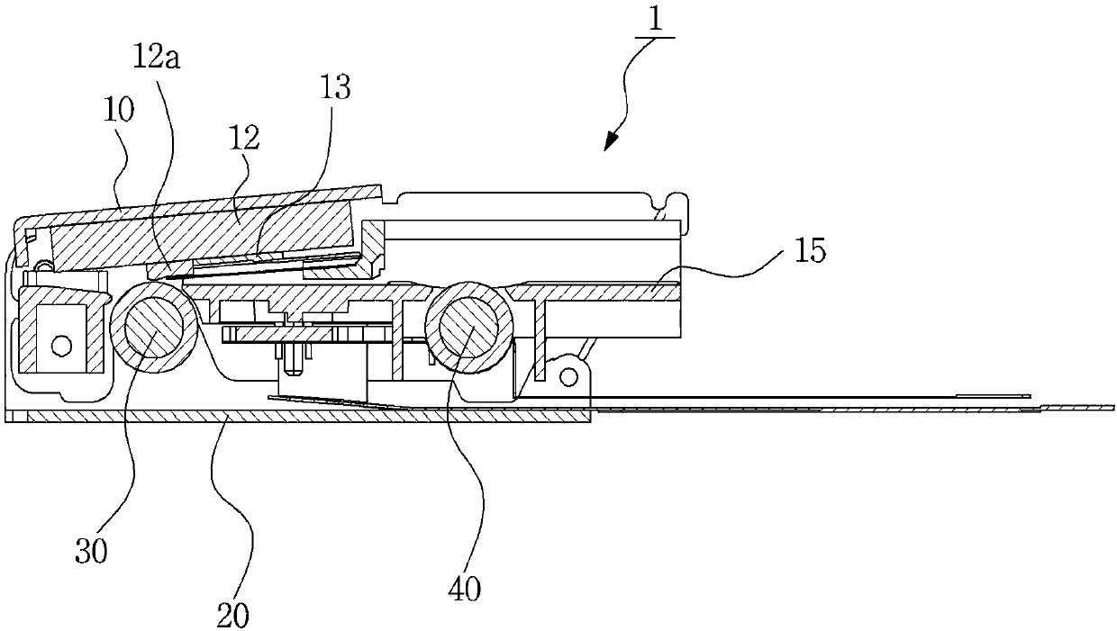
[0048] refer to Figure 4 to Figure 6 , according to an embodiment (100) of the photo printer of the present invention, comprising: a substrate (110), a pickup roller (R1) and a platen roller (R2), a head (refer to Figure 9 '143'), swing bracket (150), pressurizing part (160).
[0049] In this embodiment, the base plate (110) is formed with a paper supply part (111) that stacks and accommodates a plurality of papers, and a lower base plate (115) extending to the front side is connected to the lower part of the base plate (110), In addition, the substrate (110) and the lower substrate (115) are formed separately for ease of manufacture, and may be integrally formed.
[0050]The pickup roller ( R1 ) is for supplying forwardly the lowermost paper among the stacked paper protruding from the bottom surface of the paper supply part ( 111 ) of the base plate ( 110 ).
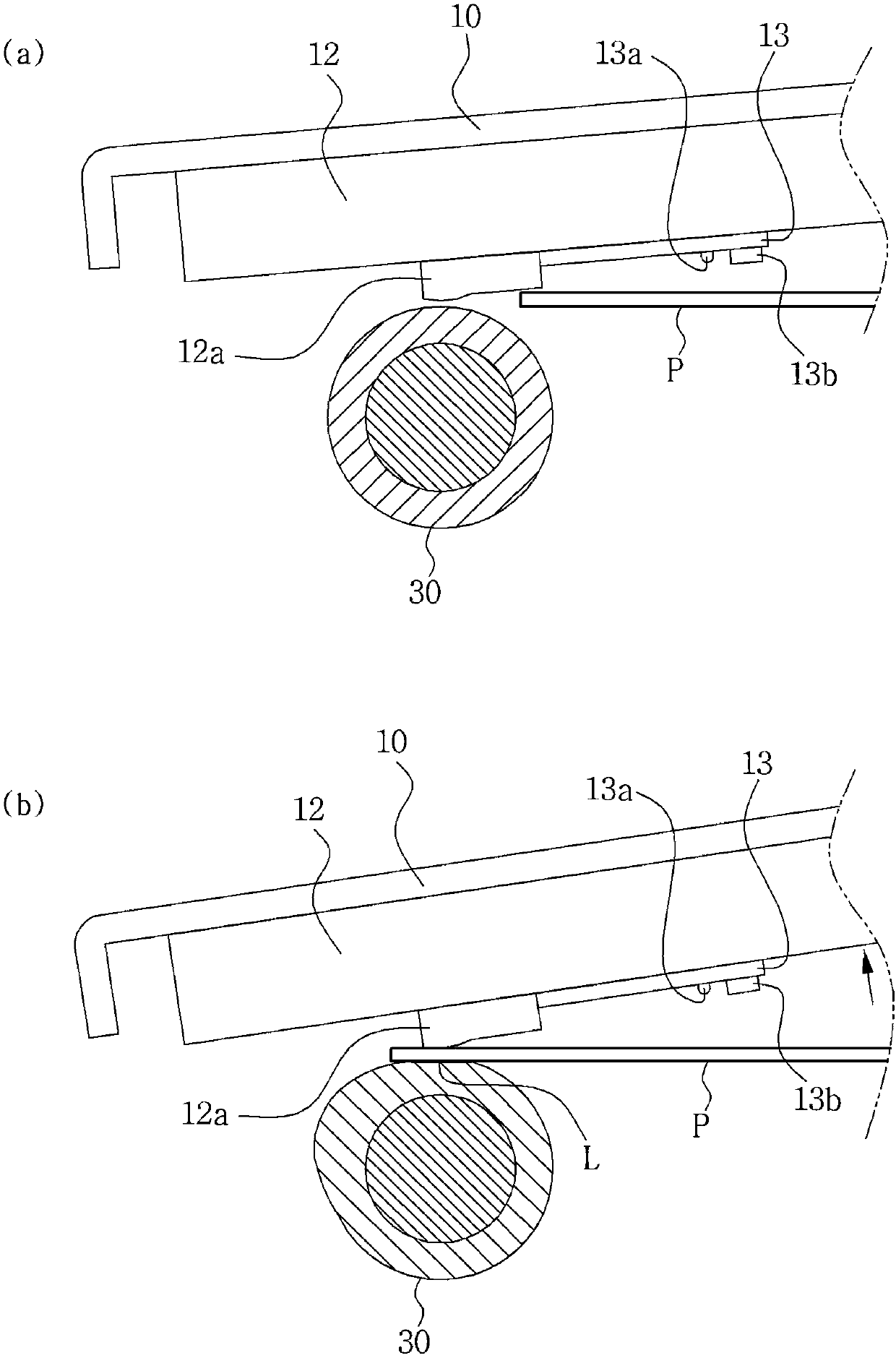
[0051] In addition, a paper pressing member (120) elastically pressing paper stacked on the paper supply unit (11...
PUM
 Abstract
Description
Claims
Application Information