A control method for an automatic control device for hydraulic energy regeneration of a front hanger

An automatic control device, a technology of hydraulic energy, applied in the directions of transportation and packaging, load hoisting components, etc., can solve the problems of reducing work efficiency, reducing the operating comfort of the driver, reducing the lifting speed of the boom, and improving the operating comfort. stability, solve the boom shock, and increase the effect of work efficiency

Active Publication Date: 2019-01-11
ANHUI HELI CO LTD
View PDF6 Cites 0 Cited by
  • Summary
  • Abstract
  • Description
  • Claims
  • Application Information

AI Technical Summary

Problems solved by technology

Because after the pressure exceeds a certain value, it is difficult for the pressure oil in the upper chamber of the cylinder to flow into the lower chamber of the cylinder, so that the hydraulic oil in the upper chamber cannot be discharged and the lifting speed of the boom will be reduced, thereby reducing the working efficiency, and in the lifting When the action stops, because the energy regeneration solenoid valve is an on-off valve, if it is suddenly closed, the hydraulic oil route in the upper chamber of the cylinder, which originally communicated with the high-pressure oil in the lower chamber of the cylinder, suddenly communicates with the hydraulic oil tank. Due to the sudden change in pressure, the boom will vibrate seriously, reducing driving operator comfort
For this reason, the driver is unwilling to use this function, and the expected energy-saving effect cannot be achieved.

Method used


Image

  • A control method for an automatic control device for hydraulic energy regeneration of a front hanger
  • A control method for an automatic control device for hydraulic energy regeneration of a front hanger
  • A control method for an automatic control device for hydraulic energy regeneration of a front hanger

Examples


Embodiment Construction

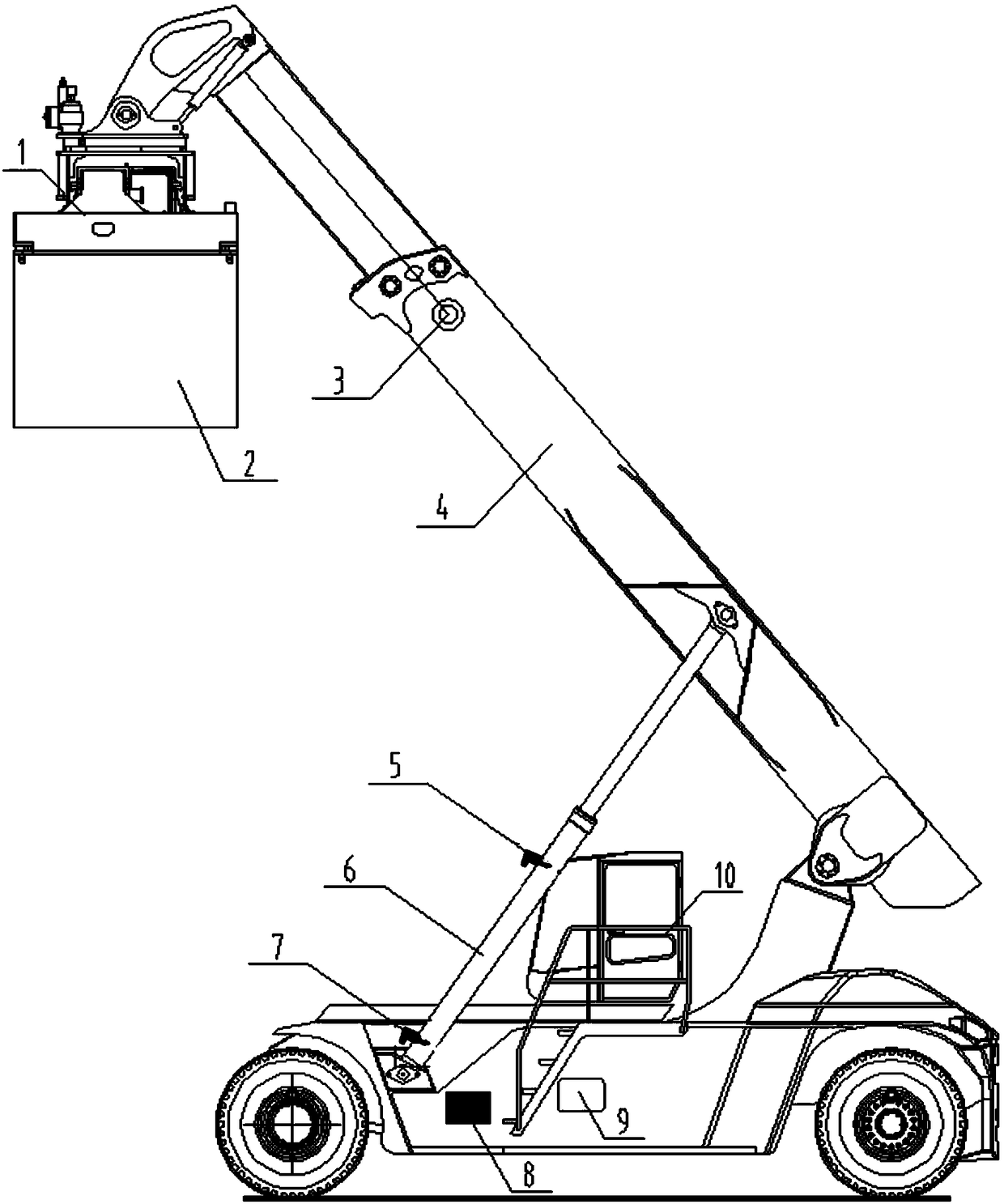
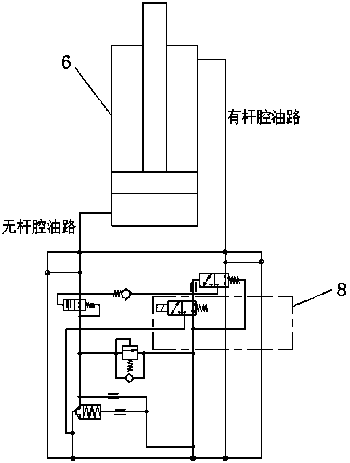
[0022] Such as figure 1 , 2 As shown, a front-mounted hydraulic energy regeneration automatic control device includes a selector switch 10 connected to a vehicle controller 9, a spreader 1, and a lifting cylinder 6 for controlling the lifting of the boom 4, and a lifting cylinder 6 arranged on the lifting cylinder 6 The energy regeneration solenoid valve 8 on the rod chamber hydraulic oil circuit, the rod chamber and the rodless chamber of the lifting cylinder 6 are respectively provided with an upper pressure sensor 5 and a lower pressure sensor 7, and the boom 4 is provided with a Detect the length and angle sensor 3 of the length of the boom 4 and the angle between it and the horizontal line; The output terminal of the vehicle controller 9 is connected to the energy regeneration solenoid valve 8 to control the opening and closing of the energy regeneration solenoid valve 8 .

[0023] In a further solution, the lifting device 1 is provided with a locking sensor for detecti...


PUM


Abstract

The invention provides a hydraulic energy regeneration automatic control device for a container front crane and a control method. The hydraulic energy regeneration automatic control device comprises aselection switch connected with a vehicle controller, a lifting appliance, a lifting oil cylinder for controlling a big arm to rise and fall, and an energy regeneration electromagnetic valve arrangedon a hydraulic oil loop of a rod cavity of the lifting oil cylinder, wherein an upper pressure sensor and a lower pressure sensor are respectively arranged in the rod cavity and a rodless cavity of the lifting oil cylinder; a length and angle sensor for detecting the length of the big arm and an included angle between the big arm and a horizontal line; the output ends of the length and angle sensor, the upper pressure sensor, the lower pressure sensor and the selection switch are connected with the input end of the vehicle controller; the output end of the vehicle controller is connected withthe energy regeneration electromagnetic valve to control opening and closing of the energy regeneration electromagnetic valve. The hydraulic energy regeneration automatic control device avoids the phenomenon of oscillation of the big arm due to closing of the energy regeneration electromagnetic valve, and also improves the working efficiency of a vehicle; meanwhile, the operation comfortablenessof a driver is improved.

Description

technical field [0001] The invention relates to an energy-saving technology for a front hanger hydraulic system, in particular to an automatic control device and control method for front hanger hydraulic energy regeneration. Background technique [0002] Reach stacker is the abbreviation of container reach crane. Reach stacker is a kind of crane used to load and unload containers. It belongs to a kind of lifting equipment, and it can also be said to be a mobile machine. The front hanger is to push the boom upwards by the lifting cylinder, and the boom drives the spreader to lift the heavy object. An energy regeneration selector switch is added to the electric control system of the front stacker. The switch is installed on the console that is easy for the driver to operate in the cab. After the switch signal enters the vehicle controller, the vehicle controller outputs a high level to control the hydraulic energy. The regenerative solenoid valve works, and when the boom is l...

Claims


Application Information

Patent Timeline
Patent Type & Authority Patents(China)
IPC IPC(8): B66C13/20
Inventor 薛振见许涛王法录张守飞吴猛
Owner ANHUI HELI CO LTD
Why Eureka
Try Eureka