
Method and system for controlling water injection

A technology of water injection and water injection, which is applied in electrical control, charging system, engine control, etc. It can solve the problems of engine load moving back and forth, reducing fuel economy, and reducing the life of parts

Active Publication Date: 2018-01-30
FORD GLOBAL TECH LLC
View PDF22 Cites 1 Cited by
  • Summary
  • Abstract
  • Description
  • Claims
  • Application Information

AI Technical Summary

Problems solved by technology

Another problem is that frequent changes in the operator's pedal demand can cause the engine load to shift back and forth, causing the water injection to turn on and off frequently
Excessive switching reduces fuel economy due to losses incurred during transitions and can reduce component life
In addition, frequent switching can cause speed / load and air-fuel ratio disturbances

Method used


Image

  • Method and system for controlling water injection
  • Method and system for controlling water injection
  • Method and system for controlling water injection

Examples


Embodiment Construction

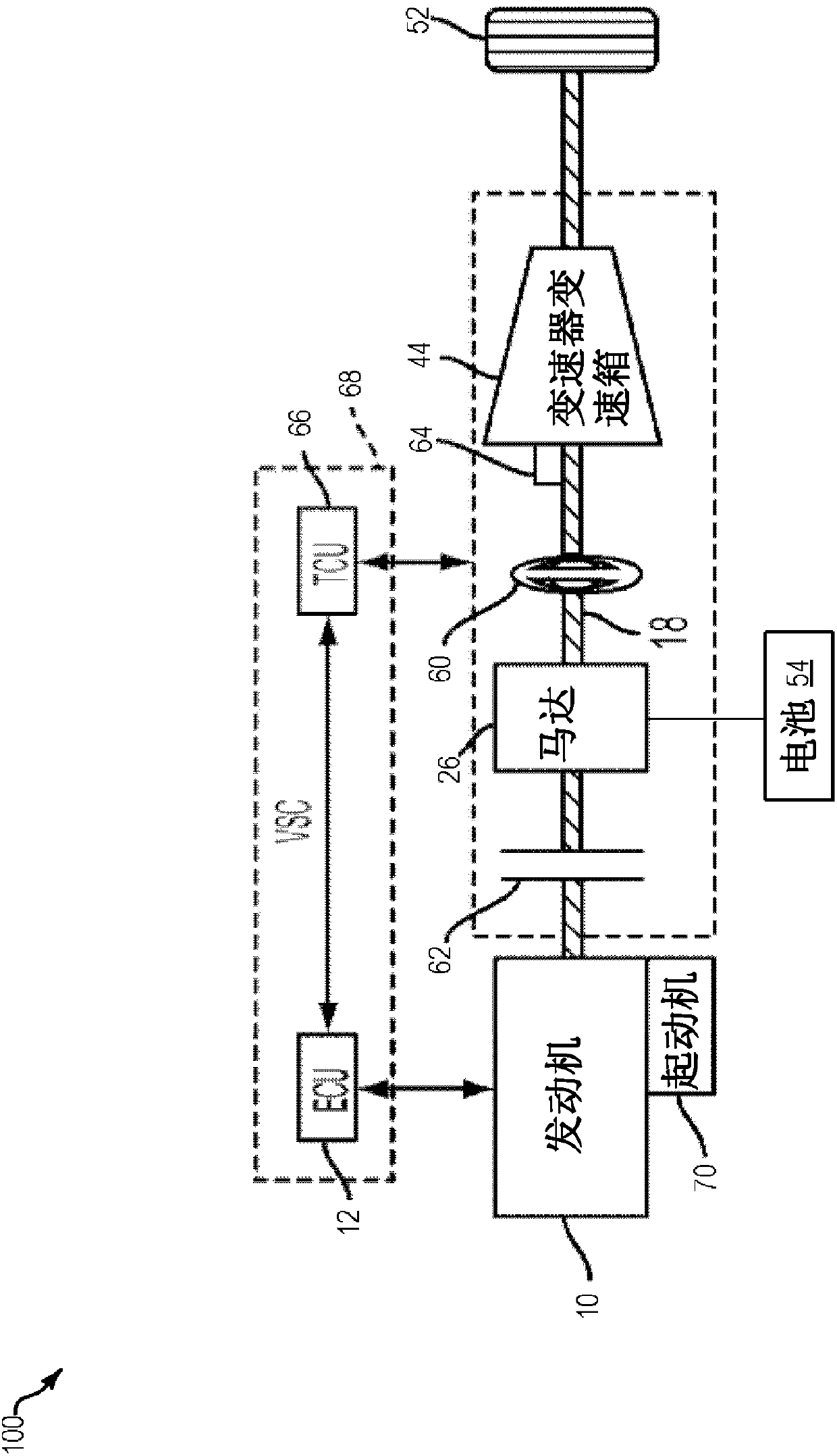
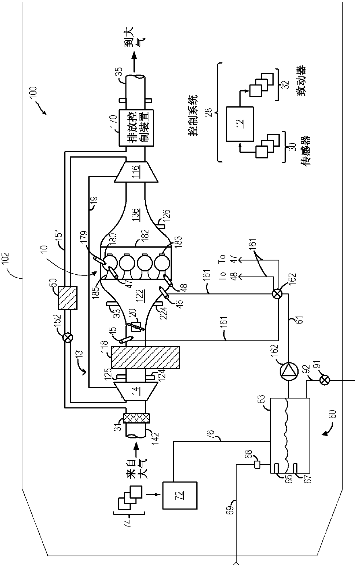
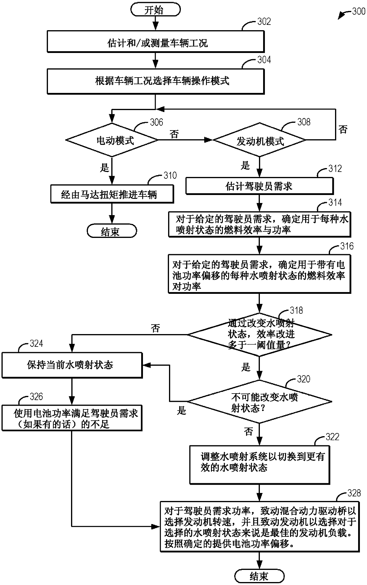
[0015] The following description relates to methods for improving a hybrid vehicle system with a hybrid transaxle such as, figure 1 Systems and methods for fuel economy in a vehicle system. The vehicle system may include an engine configured with water injection capability, as referenced figure 2 engine system described. The controller can be configured to execute control programs such as, image 3 example program) to select the water injection state (active or inactive) based on water availability, while adjusting the engine speed-load profile by adjusting the transmission ratio and battery power offset of the hybrid transaxle to better utilize water injection on Fuel economy benefits. refer to Figure 5 to Figure 6 An example graph is shown that may be used by a controller to select whether to maintain a water spray state or to transition between water spray states. Battery power offsets (both positive and negative) can be applied to overcome problems associated with o...


PUM


Abstract

The invention discloses a method and system for controlling water injection. Methods and systems are provided for synergizing the benefits of engine water injection in a hybrid vehicle system. Duringengine operation, in response to a change in a driver demand, the controller may opt to switch between water injection states while using stored power assist. The selection may be based on the combination of water injection and stored power offset that provides the highest engine efficiency.

Description

technical field [0001] The present description generally relates to methods and systems for controlling water usage of an engine coupled in a vehicle having a hybrid transaxle and an energy storage system. Background technique [0002] Internal combustion engines may include water injection systems that inject water into various locations, such as into the intake manifold upstream of the engine cylinders, or directly into the engine cylinders. Engine water injection provides various benefits, such as increased fuel economy and engine performance, and reduced engine emissions. In particular, when water is injected into the engine intake or cylinders, heat is transferred from the intake and / or engine components to evaporate the water, resulting in charge cooling. Injecting water into the intake air (eg, into the intake manifold) reduces the temperature of the intake air as well as the temperature of combustion at the engine cylinders. By cooling the intake charge, the tenden...

Claims


Application Information

Patent Timeline
IPC IPC(8): F02D19/12F02D29/02F02D41/00F02D41/02F02B47/02
CPCF02B47/02F02M25/022F02M25/0227F02M25/0228F02M25/025F02M25/03Y10S903/903B60K6/48B60K2006/4825B60K6/24Y02T10/12Y02T10/62B60W20/11B60K6/54B60W10/06B60W10/08B60W10/11F02D41/0025B60W2510/0638B60W2510/0666B60W2510/244B60W2710/0644B60W2710/083B60W2710/086B60W2710/1005B60W2710/244
Inventor T·G·里昂K·J·米勒
Owner FORD GLOBAL TECH LLC
Learn More