
Vibration reduction control method of power source and control apparatus, and P2 hybrid module

A control method and a technology of a control device, which are applied in the field of vehicles, can solve problems such as restrictions on the layout of engines and drive motors, limited layout space, and increased volume of dual-mass flywheels, so as to achieve optimal layout, reduce vibration damping requirements, and reduce volume Effect

Active Publication Date: 2018-01-30
SCHAEFFLER TECH AG & CO KG
View PDF5 Cites 8 Cited by
  • Summary
  • Abstract
  • Description
  • Claims
  • Application Information

AI Technical Summary

Problems solved by technology

[0004] Since the damping performance of a dual-mass flywheel is proportional to its mass, the increase in mass will inevitably lead to an increase in the volume of the dual-mass flywheel
For a car with a horizontal engine, the layout space is very limited, resulting in a very awkward position for the design of the dual-mass flywheel in the P2 hybrid module: if the layout requirements of the engine and drive motor are to be met, the dual-mass flywheel needs to be reduced The volume of the flywheel will affect the vibration damping performance of the P2 hybrid module; if the vibration damping performance of the P2 hybrid module is to be improved, the volume of the dual-mass flywheel must be increased, but this will also affect the arrangement of the engine and the drive motor. Very limited, while increasing the weight of the P2 hybrid module

Method used


Image

  • Vibration reduction control method of power source and control apparatus, and P2 hybrid module
  • Vibration reduction control method of power source and control apparatus, and P2 hybrid module
  • Vibration reduction control method of power source and control apparatus, and P2 hybrid module

Examples


Embodiment Construction

[0038] In order to make the above objects, features and advantages of the present invention more comprehensible, specific embodiments of the present invention will be described in detail below in conjunction with the accompanying drawings.

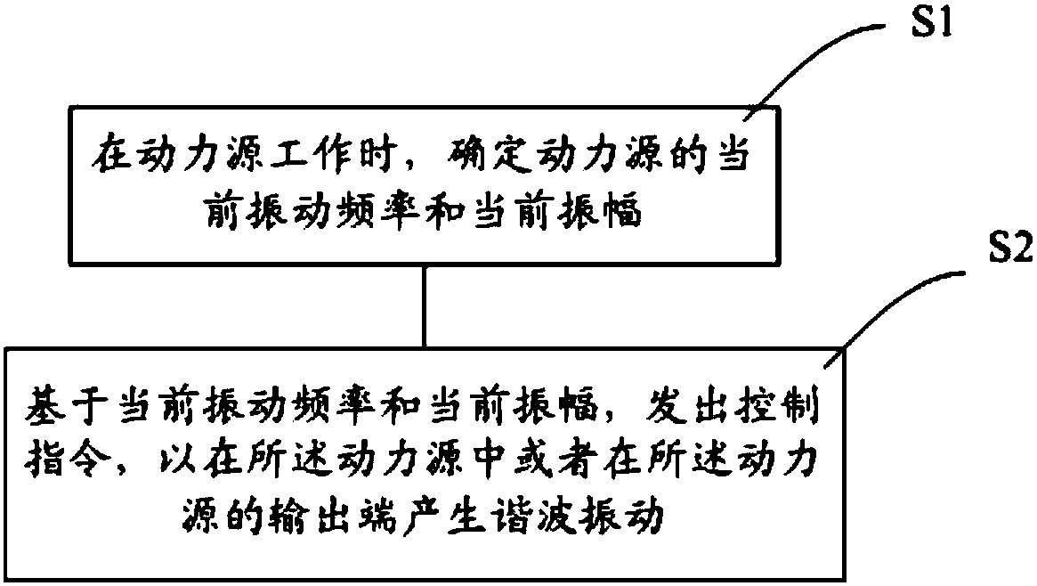
[0039] An embodiment of the present invention provides a vibration reduction control method for a power source. The power source is an engine or a drive motor. Refer to figure 1 As shown, the vibration reduction control method includes:

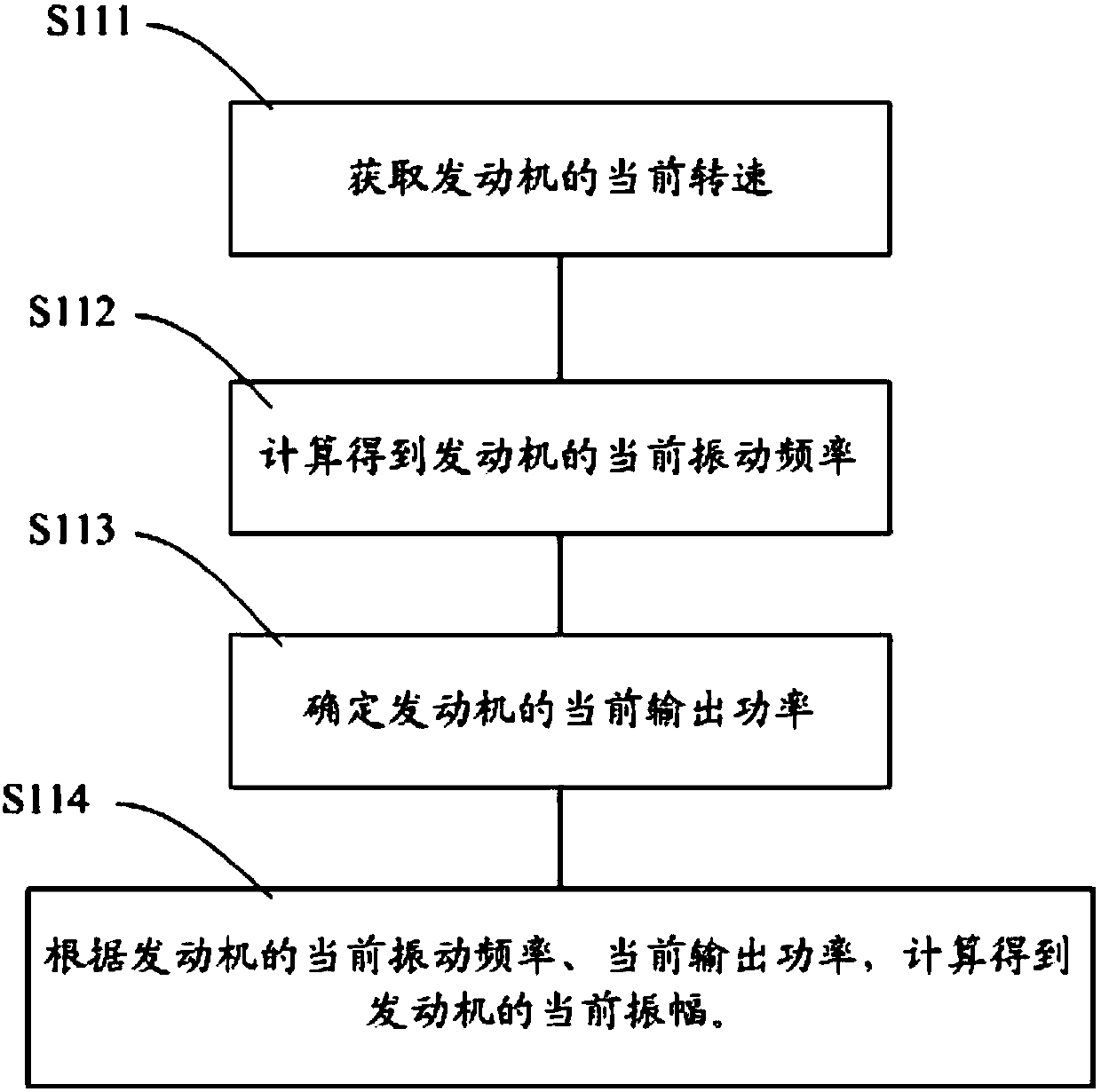
[0040] Step S1: When the power source is working, determine the current vibration frequency and current amplitude of the power source;

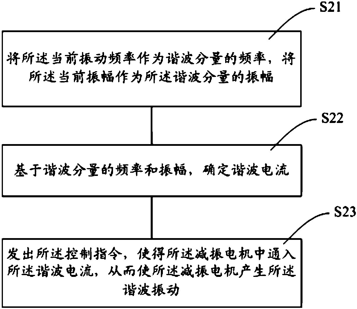
[0041] Step S2: Based on the current vibration frequency and current amplitude, issue a control instruction to generate harmonic vibration in the power source or at the output end of the power source, the vibration frequency of the harmonic vibration is the same as the current vibration frequency, and the harmonic vibration The vibration direction of the vibration is op...


PUM


Abstract

A vibration reduction control method of a power source and a control apparatus, and a P2 hybrid module are disclosed. The a power source is an engine or a driving motor. The vibration reduction control method comprises the following steps of when the power source works, determining a current vibration frequency and a current amplitude of the power source; and based on the current vibration frequency and the current amplitude, emitting a control instruction so as to generate harmonic wave vibration in the power source or on an output terminal of the power source, wherein a vibration frequency of the harmonic wave vibration is the same with the current vibration frequency, and a vibration direction is opposite to a current vibration direction of the power source. In the invention, through using the harmonic wave vibration, vibration of the power source is absorbed; in the P2 hybrid module, generated harmonic wave vibration is used to replace functions of partial or all double quality flywheels; a vibration reduction requirement of the double quality flywheels is reduced and a volume of the double quality flywheels is decreased so that a purpose of reducing a volume of the P2 hybrid module is reached; and arrangement modes of the engine and the driving motor are optimized.

Description

technical field [0001] The invention relates to the field of vehicles, in particular to a vibration reduction control method for a power source, a control device, and a P2 hybrid module. Background technique [0002] The dual-mass flywheel is a configuration that appeared on automobiles in the late 1980s, and the English abbreviation is called DMF (DoubleMass Flywheel). The dual-mass flywheel is used in the power train of the automobile, and is connected to the output end of the power source, and plays a role of vibration reduction in the power train of the car. [0003] In the P2 hybrid module, the power source includes the engine and the drive motor, and the dual-mass flywheel is located between the engine and the drive motor and connected to the output end of the engine to absorb the vibration and torque ripple generated by the engine and the drive motor during operation . Compared with the traditional powertrain with only the engine as the power source, the vibration d...

Claims


Application Information

Patent Timeline
Patent Type & Authority Applications(China)
IPC IPC(8): G05D19/02F16F15/00
Inventor 曹艺李良梓陶益
Owner SCHAEFFLER TECH AG & CO KG
Learn More