
Time-sharing sampling holding circuit

A technology of sample-and-hold circuit and hold circuit, which is applied in the direction of analog-to-digital converters, etc., can solve problems such as short signal hold time, unfavorable system performance, phase error, etc., to maximize signal hold time, improve system performance indicators, and eliminate phase effect of error

Active Publication Date: 2018-01-30
NO 24 RES INST OF CETC
View PDF3 Cites 3 Cited by
  • Summary
  • Abstract
  • Description
  • Claims
  • Application Information

AI Technical Summary

Problems solved by technology

The time-sharing sampling circuit in the prior art cannot ensure that each sampling channel samples the same analog signal at strict equal intervals, and there is a certain phase error, so the performance is poor
In addition, the signal holding time of the time-division sampling circuit in the prior art is relatively short, which is not conducive to improving system performance

Method used


Image

  • Time-sharing sampling holding circuit
  • Time-sharing sampling holding circuit
  • Time-sharing sampling holding circuit

Examples


Embodiment Construction

[0023] The preferred embodiments of the present invention will be described in detail below in conjunction with the accompanying drawings; it should be understood that the preferred embodiments are only for illustrating the present invention, rather than limiting the protection scope of the present invention.

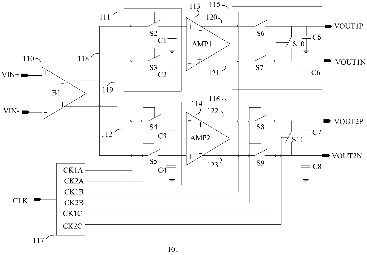
[0024] Such as figure 1 The shown time-division sample-and-hold circuit includes an input buffer 110 for receiving external differential analog signals VIN+ and VIN-. The input buffer 110 drives the first sample-and-hold circuit 111 and the second sample-and-hold circuit 112 simultaneously. The first sample and hold circuit 111 drives the first differential amplifier 113 ; the second sample and hold circuit 112 drives the second differential amplifier 114 . The first differential amplifier 113 drives the third sample-and-hold circuit 115 ; the second differential amplifier 114 drives the fourth sample-and-hold circuit 116 . The third sample-and-hold circuit 115 output...


PUM


Abstract

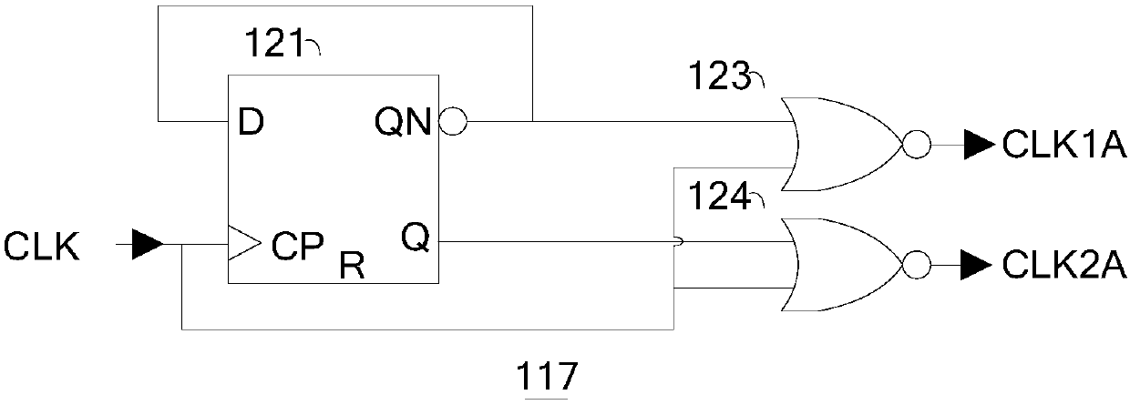
The invention relates to a time-sharing sampling holding circuit comprising an input buffer and a clock processing circuit. The input buffer drives a first sampling holding circuit and a second sampling holding circuit simultaneously and drives a first differential amplifier and a second differential amplifier respectively; the first differential amplifier drives a third sampling holding circuit;and the second differential amplifier drives a fourth sampling holding circuit. The clock processing circuit is used for receiving an external clock signal CLK and then generating clock signals; the clock signals CLK1A and CLK2A drive the first sampling holding circuit and the second sampling holding circuit respectively; the clock signals CLK1B and CLK2B drive the third sampling holding circuit and the fourth sampling holding circuit respectively; and the clock signals CLK1C and CLK2C drive the third sampling holding circuit and the fourth sampling holding circuit respectively. On the basis of the designed clock processing circuit, two sampling channels carry out sampling on analog signals strictly according to an external clock signal frequency, thereby eliminating a phase error and achieving an objective of realizing a high sampling frequency by a circuit with a low sampling frequency.

Description

technical field [0001] The invention belongs to the field of analog / mixed signal integrated circuits, in particular to a time-division sampling and holding circuit. Background technique [0002] The time-sharing sampling circuit uses more than two channels to sample the same analog signal at equal intervals to achieve the purpose of achieving a higher sampling frequency with a circuit with a lower sampling frequency. The time-sharing sampling circuit in the prior art cannot ensure that each sampling channel samples the same analog signal at strict equal intervals, and there is a certain phase error, so the performance is poor. In addition, the signal holding time of the time-division sampling circuit in the prior art is relatively short, which is not conducive to improving system performance. Contents of the invention [0003] In order to overcome the above problems, the present invention provides a time-division sample-and-hold circuit, which eliminates the phase error b...

Claims


Application Information

Patent Timeline
Patent Type & Authority Applications(China)
IPC IPC(8): H03M1/12
Inventor 胡蓉彬叶荣科张磊朱璨张正平王健安蒋和全胡刚毅
Owner NO 24 RES INST OF CETC
Learn More