A time-division sample-and-hold circuit
A sample-hold circuit and hold circuit technology, applied in the direction of analog-to-digital converters, etc., can solve the problems of short signal holding time, adverse system performance, phase error, etc., to maximize signal holding time, improve system performance indicators, and eliminate phase. effect of error
- Summary
- Abstract
- Description
- Claims
- Application Information
AI Technical Summary
Problems solved by technology
Method used
Image
Examples
Embodiment Construction
[0023] The preferred embodiments of the present invention will be described in detail below with reference to the accompanying drawings; it should be understood that the preferred embodiments are only for illustrating the present invention, rather than for limiting the protection scope of the present invention.
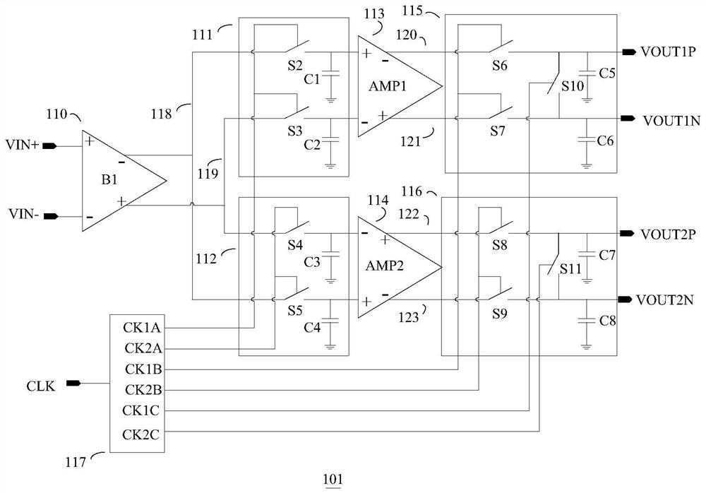
[0024] like figure 1 The illustrated time-division sample-and-hold circuit includes an input buffer 110 for receiving external differential analog signals VIN+ and VIN-. The input buffer 110 drives the first sample and hold circuit 111 and the second sample and hold circuit 112 simultaneously. The first sample and hold circuit 111 drives the first differential amplifier 113 ; the second sample and hold circuit 112 drives the second differential amplifier 114 . The first differential amplifier 113 drives the third sample and hold circuit 115 ; the second differential amplifier 114 drives the fourth sample and hold circuit 116 . The third sample-and-hold circuit 115 o...
PUM
 Abstract
Description
Claims
Application Information
 - R&D
- Intellectual Property
- Life Sciences
- Materials
- Tech Scout
- Unparalleled Data Quality
- Higher Quality Content
- 60% Fewer Hallucinations
Browse by: Latest US Patents, China's latest patents, Technical Efficacy Thesaurus, Application Domain, Technology Topic, Popular Technical Reports.
© 2025 PatSnap. All rights reserved.Legal|Privacy policy|Modern Slavery Act Transparency Statement|Sitemap|About US| Contact US: help@patsnap.com


