RF Power Measurement System

A radio frequency power and measurement system technology, applied in the direction of electric power measurement through current/voltage, etc., can solve the problems of difficult to determine impedance and power measurement error, and achieve the effect of eliminating phase error, simple structure and high measurement accuracy

Inactive Publication Date: 2017-07-28
TSINGHUA UNIV
View PDF11 Cites 0 Cited by
  • Summary
  • Abstract
  • Description
  • Claims
  • Application Information

AI Technical Summary

Problems solved by technology

However, the impedance of the RF plasma equivalent load is usually difficult to determine, which brings a large error to the power measurement

Method used


Image

  • RF Power Measurement System
  • RF Power Measurement System
  • RF Power Measurement System

Examples


Embodiment Construction

[0029] Embodiments of the present invention are described in detail below, examples of which are shown in the drawings, wherein the same or similar reference numerals designate the same or similar elements or elements having the same or similar functions throughout. The embodiments described below by referring to the figures are exemplary only for explaining the present invention and should not be construed as limiting the present invention.

[0030] A radio frequency power measurement system according to an embodiment of the present invention will be described below with reference to the accompanying drawings.

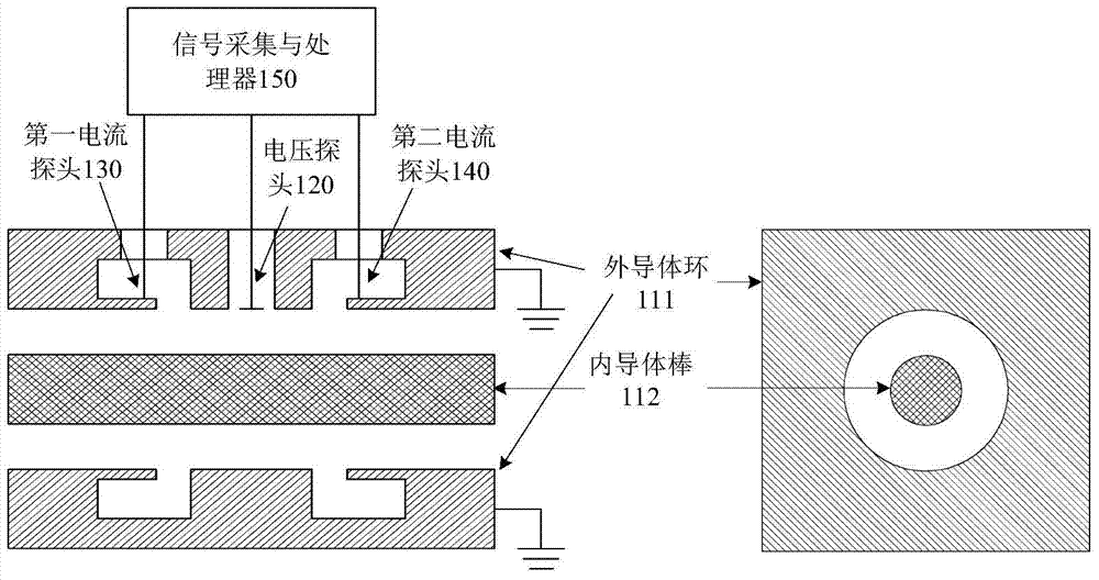
[0031] figure 1 It is a schematic structural diagram of a radio frequency power measurement system according to an embodiment of the present invention. Such as figure 1 As shown, the radio frequency power measurement system 100 (not shown in the figure) according to an embodiment of the present invention includes: a coaxial power transmission device 110 (not shown i...


PUM


Abstract

The invention provides a radio-frequency power measurement system. The radio-frequency power measurement system comprises a coaxial power transmission device, a voltage probe, a first current probe, a second current probe and a signal collecting and processing device. The coaxial power transmission device is used for transmitting radio-frequency power signals and comprises an inner conductor stick and an outer conductor ring, wherein the inner conductor stick is arranged in the outer conductor ring in a sleeved mode. The voltage probe is arranged on the outer conductor ring and used for detecting radio-frequency voltage signals of the coaxial power transmission device. The first current probe and the second current probe are arranged on the outer conductor ring and distributed on the two sides of the voltage probe in the axial direction of the inner conductor stick. The signal collecting and processing device is connected with the voltage probe, the first current probe and the second current probe so as to confirm the radio-frequency power of the radio-frequency power signals according to the radio-frequency voltage signals detected by the voltage probe and radio-frequency current signals detected by the first current probe and the second current probe. By means of the radio-frequency power measurement system, phase errors caused by the spatial distance between the voltage probe and the current probes can be eliminated, the radio-frequency power measurement system has high measurement accuracy for the radio-frequency plasma coupling power, and the radio-frequency power measurement system is simple and reliable in structure.

Description

technical field [0001] The invention relates to the field of electrical technology, in particular to a radio frequency power measurement system. Background technique [0002] RF plasma is widely used in plasma material processing processes, such as etching of semiconductor materials and plasma enhanced chemical vapor deposition. During these processes, the RF power coupled from the electrodes to the plasma is a very important control parameter that needs to be accurately measured. Usually, a voltage probe and a current are used to measure the voltage waveform and current waveform at the electrode respectively, and then the RF coupling power P (difference between incident power and reflected power) is calculated by the following formula [0003] P=|V||I|cosθ [0004] Where |V| is the effective value of the voltage, |I| is the effective value of the current, and θ is the phase difference between the voltage waveform and the current waveform. The main error of this method co...

Claims


Application Information

Patent Timeline
Patent Type & Authority Patents(China)
IPC IPC(8): G01R21/06
Inventor 高岛圭介陈文聪蒲以康
Owner TSINGHUA UNIV
Why Eureka
Try Eureka