Carrier frequency offset error elimination method and system based on specific antenna array switching sequence

A carrier frequency offset, antenna array technology, applied in the modulation carrier system, transmission system, carrier adjustment and other directions, can solve the problem of sampling data phase deviation, synchronization error, reduce the accuracy of angle estimation, etc., to eliminate the sampling data phase error Effect

Pending Publication Date: 2022-01-11
ZHEJIANG LAB
View PDF0 Cites 1 Cited by
  • Summary
  • Abstract
  • Description
  • Claims
  • Application Information

AI Technical Summary

Problems solved by technology

Due to the synchronization error between the transmitter and the receiver crystal oscillator, there is a certain degree of frequency offset in the received carrier-filtered fixed frequency spread signal
Since the antenna adopts a time-sharing switching mode, the frequency offset will cause the phase deviation of the sampling data, and the spatial spectrum angle of arrival algorithm is very sensitive to the phase of the input signal, and the frequency offset error will reduce the signal based on the spatial spectrum angle of arrival algorithm. Angle estimation accuracy for direction of arrival

Method used


Image

  • Carrier frequency offset error elimination method and system based on specific antenna array switching sequence
  • Carrier frequency offset error elimination method and system based on specific antenna array switching sequence
  • Carrier frequency offset error elimination method and system based on specific antenna array switching sequence

Examples


Embodiment Construction

[0030] The present invention will be described in detail below with reference to the accompanying drawings and preferred embodiments, and the purpose and effect of the present invention will become clearer. It should be understood that the specific embodiments described here are only used to explain the present invention and are not intended to limit the present invention.

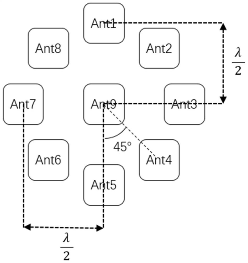
[0031] like figure 1 As shown, the receiver antenna array includes 9 patch antennas, in which antenna 9 is set as the reference antenna, and antennas 1 to 8 are array antennas that form a uniform circular array clockwise on the same plane with the reference antenna as the center. Radius is half carrier wavelength:

[0032]

[0033] The receiver of the present invention switches antennas time-divisionally to sample Bluetooth fixed frequency extension signals according to a predetermined sequence, and the single activation time of each antenna is 4 μs, in which the switching and sampling time respectively...


PUM


Abstract

The invention discloses a carrier frequency offset error elimination method and a carrier frequency offset error elimination system based on a specific antenna array switching sequence, which are applied to a Bluetooth wireless communication system. The method comprise the following steps: enabling a signal receiving end to switch a reference antenna and an array antenna in a time-sharing manner through a specific sequence to receive a Bluetooth signal; calculating the phase difference between the sampling points of which the reference antenna time interval is integer multiples of the carrier period to obtain a frequency offset error value; and carrying out phase compensation on other array antennas through the calculated phase error value. On the basis of specific receiver antenna array arrangement, a reference antenna is introduced, a specific antenna switching sequence and a phase compensation algorithm are provided, phase errors caused by carrier frequency deviation brought by asynchronous crystal oscillators of a receiver and a transmitter are eliminated, and the reduction degree of sampling signals is improved. The method is low in requirement for the number of data channels, low in calculation complexity and suitable for receiver signal processing of single-data-channel multi-antenna time-sharing switching.

Description

technical field [0001] The invention relates to the field of bluetooth communication, in particular to a carrier frequency offset error elimination method based on a specific antenna array switching sequence. Background technique [0002] With the increasing popularity of low-power Bluetooth devices, positioning using Bluetooth signals has become a hot topic in recent years. In order to better support the Bluetooth positioning function, in the Bluetooth 5.1 standard protocol, the end of each Bluetooth signal packet contains an extended signal with a fixed frequency. After the signal is filtered by the carrier, it becomes a fixed-frequency sine wave. The receiver side samples and analyzes the signal through time-sharing switching of different antennas, and estimates the incoming wave direction through the angle of arrival algorithm. Because there is a synchronization error between the crystal oscillators of the transmitter and the receiver, there is a certain degree of frequ...

Claims


Application Information

Patent Timeline
Patent Type & Authority Applications(China)
IPC IPC(8): H04L27/00
CPCH04L27/0014H04L2027/0026
Inventor 杨李杰励翔东卢昊邓庆文许桐恺沈思逸曾玉明徐志伟
Owner ZHEJIANG LAB
Why Eureka
Try Eureka