A life detection system and method based on a multi-rotor unmanned aerial vehicle

A multi-rotor UAV and life detection technology, applied in the field of life detection and rescue, can solve the problems of phase error, search and rescue range, limited flexibility, inability to accurately detect weak signals, etc., to eliminate phase error and maintain real-time performance , the effect of improving the quality

Active Publication Date: 2022-07-15
HUNAN NOVASKY ELECTRONICS TECH
View PDF7 Cites 0 Cited by
  • Summary
  • Abstract
  • Description
  • Claims
  • Application Information

AI Technical Summary

Problems solved by technology

However, at present, when life detection is realized based on the UAV platform equipped with detection radar, due to the influence of meteorological interference and the turbulence of the UAV itself during flight, it will produce severe jitter, resulting in yaw, pitch angle changes and roll, etc. These changes There will be a phase error, and the target of life detection is weak signals such as breathing, heartbeat and limb swing. Under the influence of the above-mentioned phase error, the weak signal cannot be accurately detected, that is, the life detection radar cannot work normally during the flight of the drone. , the radar cannot detect the target. Therefore, at present, the UAV is usually carried by the detection radar to fly to the designated position in the area to be measured. After the UAV is stationary, if the entire system (UAV and detection radar) is stationary The ground or roof, and then control the detection radar to search and detect the area within the coverage to ensure that the radar can work normally. However, this method must keep the radar static detection, and the scope and flexibility of search and rescue are still very limited, which is not practical. It cannot meet the rapid search needs of large-scale search and rescue activities

Method used


Image

  • A life detection system and method based on a multi-rotor unmanned aerial vehicle
  • A life detection system and method based on a multi-rotor unmanned aerial vehicle
  • A life detection system and method based on a multi-rotor unmanned aerial vehicle

Examples


Embodiment Construction

[0043] The present invention will be further described below with reference to the accompanying drawings and specific preferred embodiments, but the protection scope of the present invention is not limited thereby.

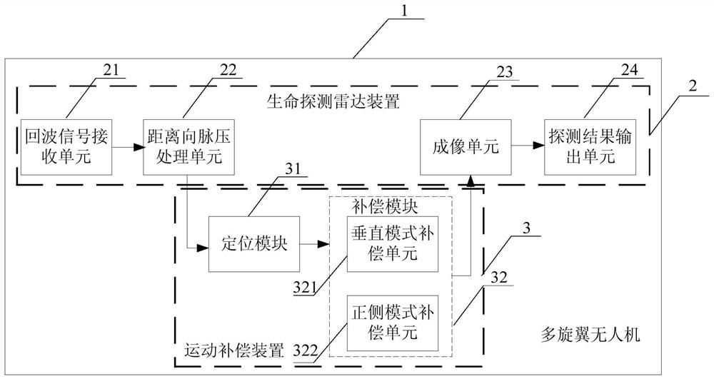
[0044] like figure 1 As shown, the life detection system based on the multi-rotor unmanned aerial vehicle in this embodiment includes a multi-rotor unmanned aerial vehicle 1 and a life detection radar device 2 mounted on the multi-rotor unmanned aerial vehicle 1, and also includes a life detection radar device 2 connected to the life detection radar device 2. Motion compensation device 3. When the multi-rotor UAV 1 is flying in the area to be tested, the life detection radar device 2 performs the detection of the living object. During the detection process of the life detection radar device 2, the motion compensation device 3 according to the multi-rotor unmanned aerial vehicle The real-time position information of the drone 1 performs motion compensation on the r...


PUM


Abstract

The invention discloses a life detection system and method based on a multi-rotor unmanned aerial vehicle. The system includes a multi-rotor unmanned aerial vehicle, a life detection radar device mounted on the multi-rotor unmanned aerial vehicle, and a motion detection radar device connected to the life detection radar device. Compensation device. When the multi-rotor UAV is flying in the area to be tested, the life detection radar device detects the life object. During the detection process of the life detection radar device, the motion compensation device adjusts the target according to the real-time position information of the multi-rotor UAV. The radar detection signal performs motion compensation to compensate for the displacement deviation caused by the jitter of the multi-rotor UAV. The invention has the advantages of simple structure, low cost, capable of realizing dynamic life detection, high detection efficiency and precision, flexible detection mode, and the like.

Description

technical field [0001] The invention relates to the technical field of life detection search and rescue, in particular to a life detection system and method based on a multi-rotor unmanned aerial vehicle. Background technique [0002] After large-scale natural disasters such as earthquakes and landslides, the most urgent task is to quickly detect and search for the specific location of the trapped and buried people, so as to organize rapid rescue of the on-site search and rescue personnel. At present, the search and rescue of rescuers is usually carried out manually by the rescuers with hand-held search equipment. The commonly used search equipment is life detectors. The search area can only be checked point by point, the search efficiency is very low, the detection area is small, and due to the need for search and rescue personnel to enter, it is also prone to secondary hazards, and the efficiency and success rate of large-scale search and rescue are low. [0003] In view ...

Claims


Application Information

Patent Timeline
Patent Type & Authority Patents(China)
IPC IPC(8): G01S13/88
CPCG01S13/88
Inventor 杨博王生水韩明华衣晓飞韩乃军唐良勇
Owner HUNAN NOVASKY ELECTRONICS TECH
Why Eureka
Try Eureka