Method and device for sending and receiving data
A technology of sending equipment and receiving equipment, applied in the direction of network traffic/resource management, electrical components, wireless communication, etc., can solve problems such as unfavorable overall network efficiency, affecting real-time operation and transmission efficiency, etc., to improve overall network efficiency and reduce Effects of Packet Complexity and Header Overhead
- Summary
- Abstract
- Description
- Claims
- Application Information
AI Technical Summary
Problems solved by technology
Method used
Image


Examples
Embodiment 1
[0153] Embodiment 1. A scheme for multiplexing data of different logical channels.
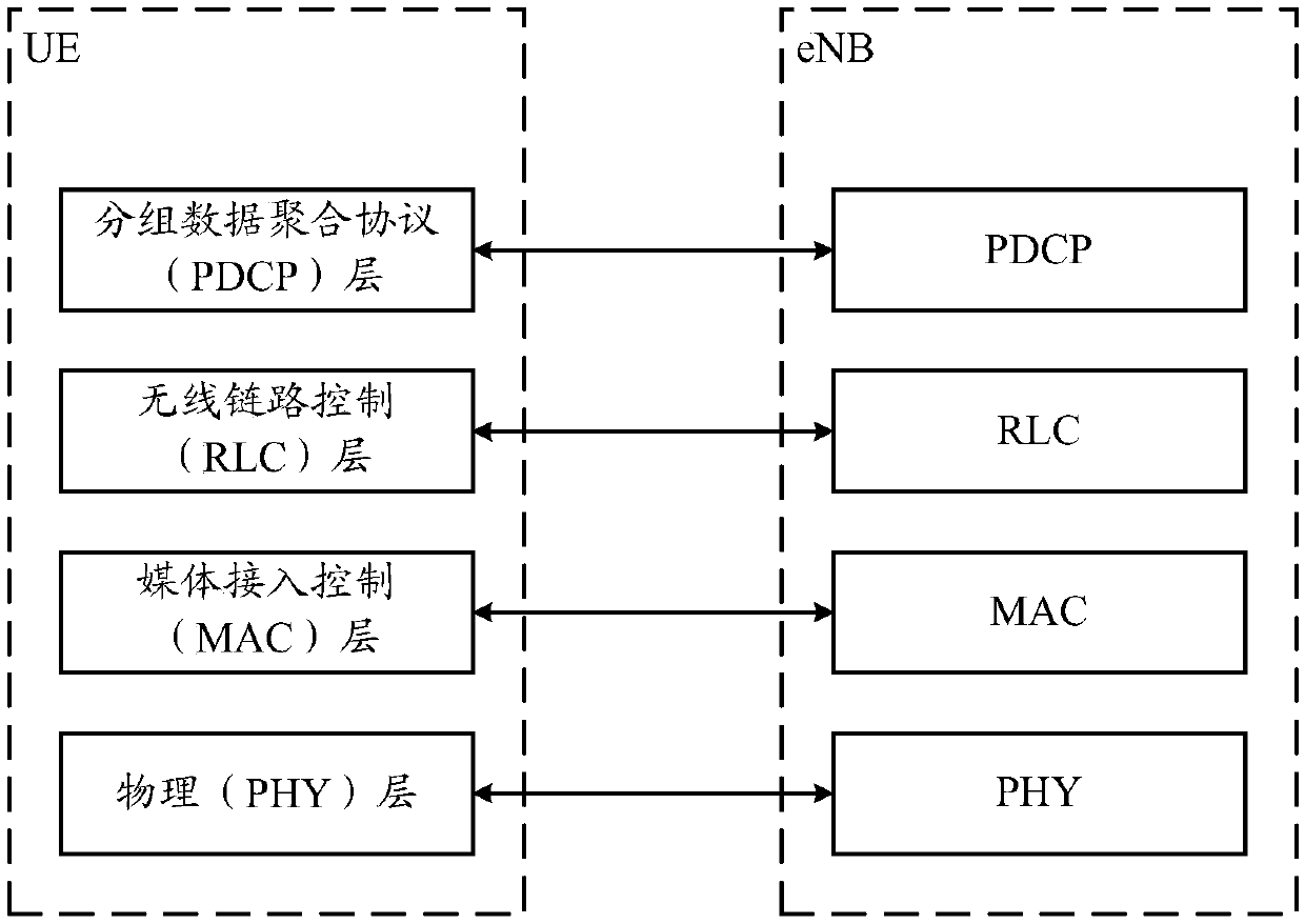
[0154] In the implementation, the data block needs to be sent to the physical layer and sent out by the physical layer, and all data can be transmitted on the physical layer resource at the same time. In order to improve transmission efficiency, the embodiment of the present invention multiplexes data of different types and from different logical channels for simultaneous transmission.
[0155] In order to improve the efficiency of data multiplexing, reduce header overhead as much as possible and maintain flexibility, multiplexing of different logical channels in the embodiment of the present invention can adopt some or all of the following methods:
[0156] 1. The sending device puts data from different logical channels into PDUs, and distinguishes them by logical channel identifiers (such as logical channel numbers). After the data packets of one logical channel are placed, the data of the n...
Embodiment 2
[0182] Embodiment 2, the first scheme for transmitting internal data packets of a logical channel.
[0183] Inside a logical channel, there may be control information, initial transmission data, and retransmission data at the logical channel level. The control information at the logical channel level here is different from the control information in Embodiment 1 above. The control information in Embodiment 1 is UE-level control information, while the control information referred to in Embodiment 2 is control information at the logical channel level. , such as some status report feedback in AM mode, header compression control information, etc.
[0184] When the sending device organizes the data blocks in a logical channel, the control information generally has the highest priority, the retransmission data takes the second place, and the initial transmission data has the lowest priority. First, then the retransmission data, and finally the initial transmission data.
[0185] A...
Embodiment 3
[0199] Embodiment 3, the second scheme for transmitting internal data packets of a logical channel.
[0200] Similar to Embodiment 2, Embodiment 3 also provides an organization method of data packets within a logical channel. Regarding control information, retransmission data, priority of initial transmission data, and order of placement, they are consistent with Embodiment 2.
[0201] In Embodiment 3, the sending device concentrates the headers in the sub-headers, followed by real control information and data payloads.
[0202] A possible PDU structure is listed below, such as Figure 5 shown. It should be noted, Figure 5 The shown structure is only a possible implementation manner, as long as the PDU structure capable of multiplexing is applicable to the embodiment of the present invention.
[0203] Figure 5 In , the meanings and values of each field are consistent with those in Embodiment 2 and Embodiment 1. The difference is that the header indication information...
PUM
 Abstract
Description
Claims
Application Information
 - Generate Ideas
- Intellectual Property
- Life Sciences
- Materials
- Tech Scout
- Unparalleled Data Quality
- Higher Quality Content
- 60% Fewer Hallucinations
Browse by: Latest US Patents, China's latest patents, Technical Efficacy Thesaurus, Application Domain, Technology Topic, Popular Technical Reports.
© 2025 PatSnap. All rights reserved.Legal|Privacy policy|Modern Slavery Act Transparency Statement|Sitemap|About US| Contact US: help@patsnap.com