Baric ballistic shock wave therapeutic apparatus with shock head buffering structure

A buffer structure and impact head technology, applied in physical therapy, massage auxiliary products, vibration massage, etc., can solve the problems affecting the life of the bullet and the depth of the shock wave, and achieve the effect of reducing pressure and improving life.

Pending Publication Date: 2018-02-02
深圳市优力威医疗科技有限公司
View PDF0 Cites 0 Cited by
  • Summary
  • Abstract
  • Description
  • Claims
  • Application Information

AI Technical Summary

Problems solved by technology

[0003] When the equipment is working, the projectile hits the impact head. Since the original design is to transmit the shock wave energy through the deformation and displac

Method used


Image

  • Baric ballistic shock wave therapeutic apparatus with shock head buffering structure
  • Baric ballistic shock wave therapeutic apparatus with shock head buffering structure
  • Baric ballistic shock wave therapeutic apparatus with shock head buffering structure

Examples


Embodiment 1

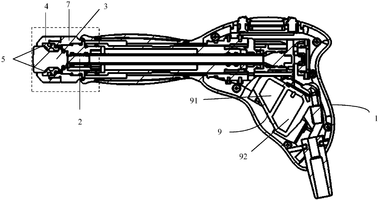
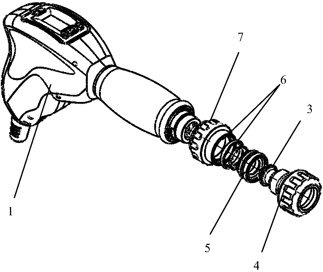
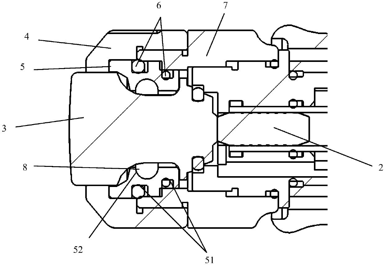
[0025] like Figure 1-6 A pneumatic ballistic shock wave therapy instrument with impact head buffer structure shown includes a handle shell 1, a projectile body 2, an impact head 3 and a shell front cover 4, and the shell front cover 4 is arranged at the front end of the handle shell 1, The impact head 3 is arranged in the shell front cover 4, the projectile body 3 is arranged in the trajectory of the handle shell 1, and is driven by compressed air to impact the impact head 3, and the impact head 3 is provided with a buffer structure, The buffer structure includes a buffer collar 5 and at least two first O-rings 6, the buffer collar 5 is sleeved on the impact head 3, and the buffer collar 5 is provided around the circumferential direction of the impact head 3 There are at least two first annular grooves 51 , and each first O-ring 6 is sleeved on each first annular groove 51 .

[0026] The motion process of present embodiment 1 is, as figure 1 As shown, the first step: the bu...

Embodiment 2

[0030] Further, such as figure 1 , figure 2 As shown, it also includes an adapter ring 7, the front cover of the shell 4 is connected to the front end of the handle shell 1 through the adapter ring 7, and one end of the buffer collar 5 is interference-fitted with the inside of the adapter ring 7, so that The other end of the buffer collar 5 is in interference fit with the inside of the shell front cover 4 .

[0031] Adopting the above technical solution further prevents the impact head 3 from rushing out of the shell front cover 4 due to inertia after being impacted by the bullet body 2 .

[0032] Further, such as Figure 3-5 As shown, the number of the first annular grooves 51 is two, and the two first annular grooves 51 are parallel to each other.

[0033] With this technical solution, the buffer collar 5 is divided into three-stage buffer structures because it has two first buffer grooves 51 parallel to each other. , to reduce the loss of shock wave energy transfer pro...

Embodiment 3

[0041] On the basis of Embodiment 1, the compressed air storage mechanism can also be improved. like figure 1 As shown, the handle housing 1 is also provided with a buffer air chamber 9 for storing compressed air, and the buffer air chamber 9 includes a first air chamber 91 and a second air chamber 92, and the first air chamber 91 and the second air chamber The chambers 92 communicate with each other through vent holes.

[0042] The use of two-stage buffer air chambers makes the storage capacity of compressed air more sufficient, and also makes the pressure of compressed air more stable.


PUM


Abstract

The invention relates to a pneumatic ballistic shock wave therapy instrument with a shock head buffer structure, which comprises a handle shell, a projectile body, an impact head and a front cover of the shell, the front cover of the shell is arranged at the front end of the handle shell, and the impact head is arranged at the front end of the handle shell. In the front cover of the shell, the projectile body is arranged in the trajectory of the handle shell, and is driven by compressed air to impact the impact head. The impact head is provided with a buffer structure, and the buffer structure includes a buffer collar and at least two A first O-ring, the buffer collar is set on the impact head, the buffer collar is provided with at least two first annular grooves around the circumferential direction of the impact head, each of the first O-rings respectively sleeved on the first annular grooves. The invention enables the shock wave generated by the projectile body to be transmitted to the impact head to the greatest extent; and reduces the pressure of the projectile body through the buffer structure, thereby greatly improving the service life of the projectile body.

Description

technical field [0001] The invention relates to a shock wave therapeutic apparatus, in particular to an air pressure ballistic shock wave therapeutic apparatus with an impact head buffer structure. Background technique [0002] At present, the impact head in the handle of the air pressure ballistic shock wave therapy instrument on the market is all sealed and deformed by O-ring. [0003] When the equipment is working, the projectile hits the impact head. Since the original design is to transmit the shock wave energy through the deformation and displacement of the O-ring, a large amount of energy will be absorbed by the projectile and the O-ring, which will affect the life of the projectile and the depth of the shock wave. Contents of the invention [0004] The purpose of the present invention is to provide a pneumatic ballistic shock wave therapy instrument with a shock head buffer structure, so that the shock wave generated by the projectile body can be transmitted to the...

Claims


Application Information

Patent Timeline
IPC IPC(8): A61H23/00
CPCA61H23/008A61H2201/0165
Inventor 刘亚军张大春李刚潘文杰
Owner 深圳市优力威医疗科技有限公司
Why Eureka
Try Eureka