
Magnetic track brake and magnetic suspension train

A technology of magnetic rail brakes and magnetic levitation trains, which is applied in the directions of brakes, railway braking systems, railway car body parts, etc. where the braking elements interact with the rails, and can solve the problem of reduced braking force of the magnetic rail brakes, large width and small thickness, etc. problems, to achieve the effect of improving operational safety

Active Publication Date: 2018-02-02
CRRC QINGDAO SIFANG ROLLING STOCK RES INST
View PDF7 Cites 4 Cited by
  • Summary
  • Abstract
  • Description
  • Claims
  • Application Information

AI Technical Summary

Problems solved by technology

[0004] At present, the tracks of maglev trains mainly include F-shaped rails and rectangular rails. The rectangular rails are characterized by smaller thickness but larger width, which are suitable for medium and high-speed maglev trains (travel speed greater than or equal to 200km / h), while the existing technology The magnetic rail brakes used by medium rail trains are generally in the form of bipolar shoes. If the magnetic rail brakes used for rail trains in the prior art are applied to maglev trains with rectangular rails, the thickness of the rectangular rails is smaller than the rails of the rail trains, resulting in Fewer lines of flux circulate in the rectangular track, which in turn reduces the braking force of the magnetic track brake

Method used


Image

  • Magnetic track brake and magnetic suspension train
  • Magnetic track brake and magnetic suspension train
  • Magnetic track brake and magnetic suspension train

Examples


Embodiment Construction

[0026] In the following, the present invention will be specifically described through exemplary embodiments. It should be understood, however, that elements, structures and characteristics of one embodiment may be beneficially incorporated in other embodiments without further recitation.

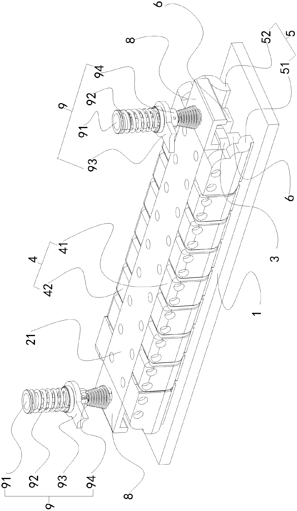
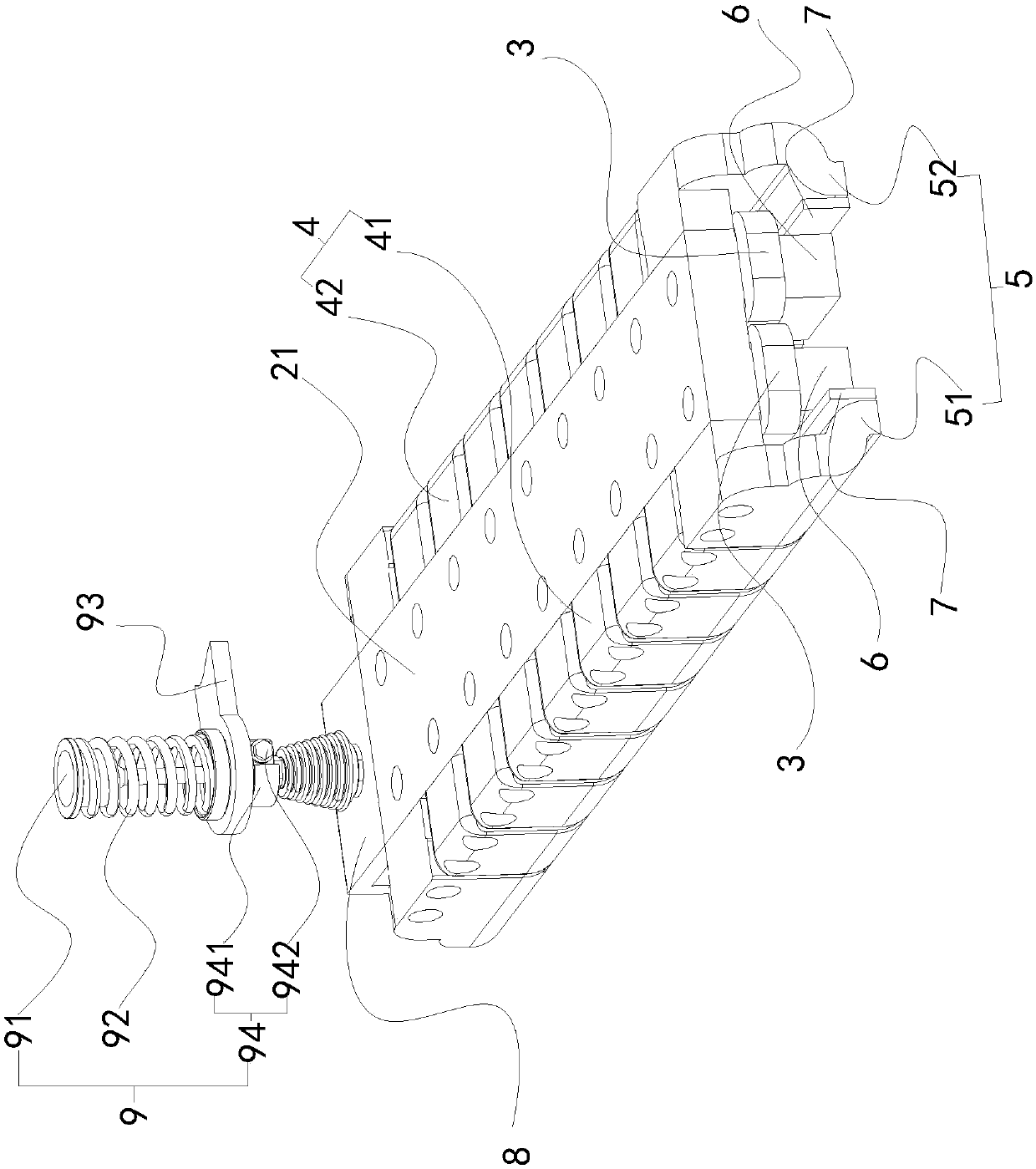
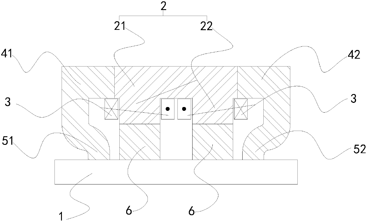
[0027] In the description of the present invention, it should be noted that the transverse direction of the iron core body and the rectangular track refers to the width direction of the iron core body and the rectangular track respectively, namely image 3 , Figure 4 The horizontal direction in ; the longitudinal direction of the iron core body and the rectangular track respectively refers to the long side direction of the iron core body and the rectangular track, namely image 3 , Figure 4 The direction perpendicular to the paper; the orientation or positional relationship indicated by the terms "inner", "outer", "upper", "lower", "front", "rear" etc. are based on the positional relatio...


PUM


Abstract

The invention provides a magnetic track brake and a magnetic suspension train. The magnetic track brake is arranged on the magnetic suspension train with a rectangular track. The magnetic track brakecomprises an iron core unit, the side, facing the rectangular track, of the iron core unit is wound with magnet exciting coils, and the opposite sides of the iron core unit are connected with a side plate unit. The end, facing the rectangular track, of the side plate unit is connected with an outer pole shoe unit. The multiple magnet exciting coils are arranged in the direction relative to the side plate unit, the side, facing the rectangular track, of the iron core unit is connected with a plurality of inner pole shoes, and the inner pole shoes are arranged corresponding to the magnet exciting coils in the direction relative to the side plate unit. The magnetic suspension train is provided with the magnetic track brake. The magnetic track brake can provides enough braking force for the magnetic suspension train in high-speed operation, and the magnetic suspension train has high operation safety accordingly.

Description

technical field [0001] The invention belongs to the technical field of magnetic levitation trains, in particular to a magnetic track brake and a magnetic levitation train. Background technique [0002] The maglev train is a modern high-tech rail vehicle. It uses electromagnetic force to achieve non-contact suspension and guidance between the train and the track, and then uses the electromagnetic force generated by the linear motor to drive the train. The mechanical braking forms of maglev trains mainly include hydraulic braking and eddy current braking. Among them, hydraulic braking performs braking through friction with the rail surface. , the friction coefficient between it and the rail surface is significantly reduced, so the braking force is also reduced, and the heat capacity of the brake pad is also difficult to meet the requirements. In addition, there are environmental pollution problems such as oil leakage; eddy current braking is a non-contact brake. It uses the p...

Claims


Application Information

Patent Timeline
Patent Type & Authority Applications(China)
IPC IPC(8): B61H7/08
CPCB61H7/08
Inventor 王明星陈传彬尹崇宏杨磊刘帅张彦伟董振威
Owner CRRC QINGDAO SIFANG ROLLING STOCK RES INST
Learn More