Method for replacing tower foot of transmission tower

A replacement method, a technology for iron towers, applied to towers, building types, buildings, etc., can solve the problems of large construction area, high work intensity, temporary power outages, etc., to reduce the construction area and reduce the workload , Guarantee the effect of normal electricity consumption

Active Publication Date: 2018-02-02
JINZHOU ELECTRIC POWER SUPPLY COMPANY OF STATE GRID LIAONING ELECTRIC POWER SUPPLY +1
View PDF5 Cites 3 Cited by
  • Summary
  • Abstract
  • Description
  • Claims
  • Application Information

AI Technical Summary

Problems solved by technology

The excavation of temporary cable pits also needs to involve the issue of temporary land occupation, and the obstruction of local people will bring obstacles to the construction
At the same time, there are also potential safety hazards. If the operation is not done properly during the construction process, it is easy to cause a tower collapse accident. The construction cost is 10,000 to 15,000 yuan
[0006] To sum up, the existing methods for replacing the feet of transmission towers have high work intensity, large construction area, high labor costs, and temporary power outages, which affect the normal power consumption of enterprises and residents.

Method used


Image

  • Method for replacing tower foot of transmission tower
  • Method for replacing tower foot of transmission tower

Examples


Embodiment Construction

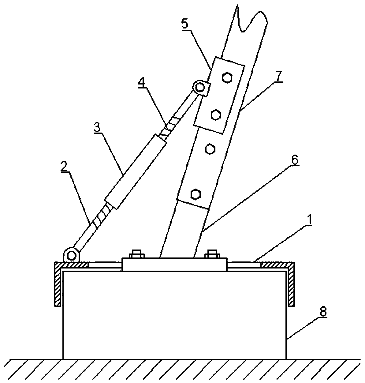
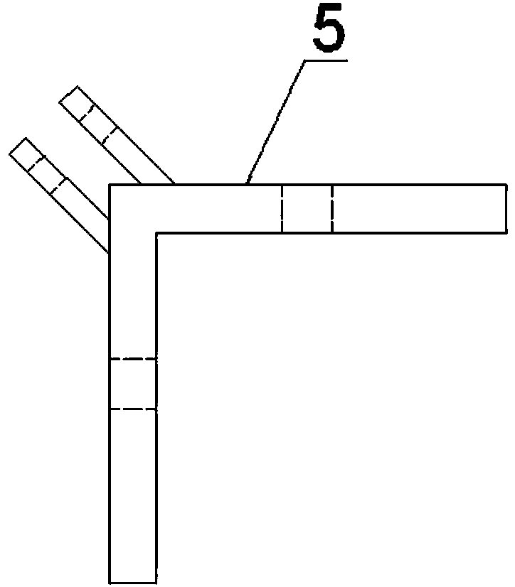
[0025] Such as figure 1 , figure 2 As shown, a transmission tower foot and main iron replacement method, the specific steps are as follows:

[0026] 1. Connect the support device between the tower foot where the tower foot 6 is to be replaced and the main iron 7. The support device includes a square frame-shaped support hoop seat 1, and the first screw rod is hinged on the top surface of the support hoop seat 1 through a pin shaft 2. Install the threaded sleeve 3 on the top of the first screw rod 2, and install the second screw rod 4 on the inner top of the threaded sleeve 3. The upper and lower thread directions of the threaded sleeve 3 are opposite, and the corresponding first screw rod 2 and the second screw rod The thread direction of the second screw mandrel 4 is opposite, and the support connector 5 is articulated at the top of the second screw mandrel 4 by a pin shaft. The support hoop seat 1 is installed on the tower base 8 where the tower foot 6 is to be replaced, ...


PUM


Abstract

A method for replacing a tower foot of a transmission tower is characterized in that the method comprises the following specific steps that 1, a supporting device is connected to the position betweenthe tower foot where a to-be-replaced tower foot is located and main iron; 2, a steel wire protective rope is connected to the position between the main iron where the to-be-replaced tower foot is located and the bottom of the supporting device in a fastened mode, and the main iron where the to-be-replaced tower foot is located is supported through the supporting device; 3, a main iron bolt and atower footing bolt which are connected to the to-be-replaced tower foot are disassembled, and the to-be-replaced tower foot is removed; 4, dust on the upper surface of a tower footing where the to-be-replaced tower foot is located is cleaned up, the main iron where the to-be-replaced tower foot is located is subjected to rust removing, and the main iron is coated with anti-rust paint; 5, the new tower foot is installed on the upper surface of the tower footing through the tower footing bolt, and the upper end of the new tower foot is connected to the main iron through the main iron bolt; and 6, the supporting device and the steel wire protective rope which are connected to the position between the tower footing and the main iron are disassembled. According to the method for replacing the tower foot of the transmission tower, the operating strength can be reduced, the construction occupied area is decreased, the labor cost is reduced, electrified replacement is achieved, and normal electricity utilization of enterprises and residents is ensured.

Description

technical field [0001] The invention relates to a method for overhauling a power transmission tower, in particular to a method for replacing a foot of a power transmission tower. Background technique [0002] With the rapid development of the national economy and the continuous progress of society, the requirements for power supply enterprises are getting higher and higher, and the requirements for safe operation of transmission lines and reliable power supply are also increasing. However, transmission lines have been exposed to the air for a long time, exposed to wind and sun all year round, and are often eroded by wind, rain, snow, and frost, resulting in the corrosion of transmission tower feet, which has brought hidden dangers to the safe operation of transmission lines. If the foot of the transmission tower is slightly corroded, it is generally necessary to brush the anti-rust paint on the foot of the transmission tower after derusting. When the corrosion is serious, th...

Claims


Application Information

Patent Timeline
Patent Type & Authority Applications(China)
IPC IPC(8): E04H12/00E04H12/22
CPCE04H12/00E04H12/22
Inventor 崔吉生李卫民王军王恩祥张凯李勇
Owner JINZHOU ELECTRIC POWER SUPPLY COMPANY OF STATE GRID LIAONING ELECTRIC POWER SUPPLY
Why Eureka
Try Eureka