PoE power receiving method, device and system

An electrical method and power supply technology, applied in the direction of data switching current source, data exchange details, etc., can solve the problems of product performance degradation, restart problem, product cost increase, etc., to reduce power consumption, improve user experience, and circuit structure simple low effect

Inactive Publication Date: 2019-10-22
TP-LINK
View PDF5 Cites 8 Cited by
  • Summary
  • Abstract
  • Description
  • Claims
  • Application Information

AI Technical Summary

Problems solved by technology

However, increasing the rated current value of the power supply equipment will greatly increase the cost of the product, and cannot solve the restart problem caused by the input voltage of the terminal equipment being lower than the rated value; directly reduce the power consumption of the terminal equipment, when the user uses a short network cable for power supply, Product performance will also degrade

Method used


Image

  • PoE power receiving method, device and system
  • PoE power receiving method, device and system
  • PoE power receiving method, device and system

Examples


Embodiment 1

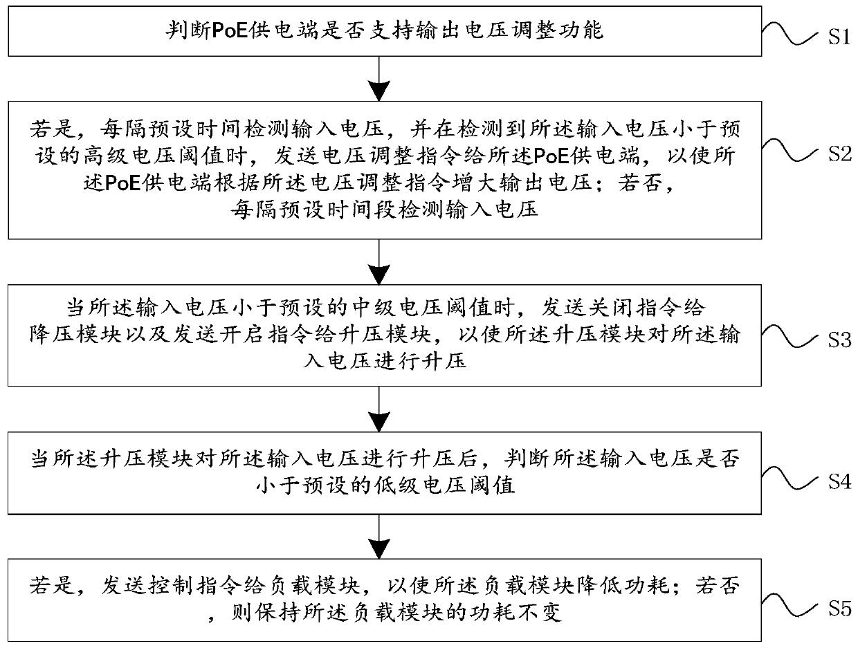
[0051] see figure 1 , figure 1 It is a flowchart of a PoE power receiving method provided by an embodiment of the present invention; including:

[0052] S1. Determine whether the PoE power supply terminal supports the output voltage adjustment function;

[0053] S2. If so, detect the input voltage every preset time, and when it is detected that the input voltage is lower than the preset advanced voltage threshold, send a voltage adjustment command to the PoE power supply terminal, so that the PoE power supply terminal The above voltage adjustment command increases the output voltage; if not, the input voltage is detected every preset time period;

[0054] S3. When the input voltage is lower than the preset intermediate voltage threshold, send a shutdown command to the step-down module and a turn-on command to the boost module, so that the boost module boosts the input voltage; wherein, the intermediate voltage threshold is less than the advanced voltage threshold;

[0055]...

Embodiment 2

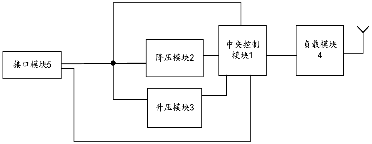
[0100] see image 3 , image 3 It is a schematic structural diagram of the first PoE power receiving device 20 provided by the embodiment of the present invention; the PoE power receiving device 20 includes a central control module 1, a step-down module 2, a boost module 3 and a load module 4; wherein, the The central control module 1 is respectively connected to the step-down module 2, the boost module 3 and the load module 4, and the central control module 1 executes the PoE power receiving method in the first embodiment above, specifically the central control For the working process of the module 1, please refer to the working process of the PoE power receiving method described in the above-mentioned embodiments, which will not be repeated here.

[0101] Further, the PoE power receiving device 20 also includes an interface module 5, the interface module 5 is used to connect the PoE power supply end, and the interface module 5 is also used to connect the step-down module 2,...

Embodiment 3

[0121] see Figure 6 , Figure 6 It is a schematic structural diagram of a PoE power receiving system provided by an embodiment of the present invention. The PoE power receiving system includes a PoE power supply end 10 and a PoE power receiving end, the PoE power supply end 10 is connected to the PoE power receiving end, and the PoE power receiving end is the PoE power receiving device 20 .

[0122] Preferably, the PoE power supply end 10 also communicates with the PoE power receiving end through the RJ45 interface. For the specific working process of the PoE power receiving end, please refer to the working process of the PoE power receiving device 20 described in the above embodiment. I won't repeat them here.

[0123] Compared with the prior art, the PoE power receiving system disclosed in the present invention solves the problem that increasing the rated current value of the power supply equipment in the prior art will greatly increase the product cost, and reducing the ...


PUM


Abstract

The invention discloses a PoE power receiving method. The method comprises the following steps: judging whether a PoE power supply end supports an output voltage adjusting function or not; if yes, detecting the input voltage every other preset time, and when it is detected that the input voltage is smaller than a preset advanced voltage threshold value, sending a voltage adjusting instruction to the PoE power supply end; if not, detecting the input voltage every other preset time period; when the input voltage is smaller than a preset intermediate voltage threshold value, sending a closing instruction to the voltage reduction module, and sending a starting instruction to the voltage boosting module, so that the voltage boosting module boosts the input voltage; after the boosting module boosts the input voltage, judging whether the input voltage is smaller than a preset low-level voltage threshold value or not; if yes, sending a control instruction to the load module to enable the loadmodule to reduce power consumption; and if not, keeping the power consumption of the load module unchanged. The invention also discloses a PoE power receiving device and a PoE power receiving system.The device can be suitable for Ethernet power receiving equipment which is long in distance and high in installation height, and is simple in circuit structure and low in implementation cost.

Description

technical field [0001] The present invention relates to the technical field of power supply, in particular to a PoE power receiving method, device and system. Background technique [0002] For Ethernet communication, ordinary Category 5 lines are used for communication, and the maximum transmission distance of data signals can reach 150-200m. When the Ethernet terminal equipment adopts Passive PoE (Power Over Ethernet, non-standard PoE) power supply mode, the network cable not only needs to transmit the network data signal, but also needs to transmit the DC voltage signal of the PoE power supply (PoE power supply terminal, such as a power adapter) to the terminal equipment ( receiving end). The voltage drop on the resistance of the long network cable will cause the DC voltage of the terminal equipment to drop. The longer the network cable, the greater the resistance of the network cable and the greater the voltage drop. Since the power consumption of the terminal equipment...

Claims


Application Information

Patent Timeline
Patent Type & Authority Applications(China)
IPC IPC(8): H04L12/10
CPCH04L12/10
Inventor 吴普超梁凯
Owner TP-LINK
Why Eureka
Try Eureka