

Blood detector
A blood tester and blood technology, which is applied in the field of blood testers, can solve the problems of not being able to meet the requirements of efficiency, slow test speed, etc.
- Summary
- Abstract
- Description
- Claims
- Application Information
AI Technical Summary
Problems solved by technology
Method used
Image

Examples
Embodiment 1
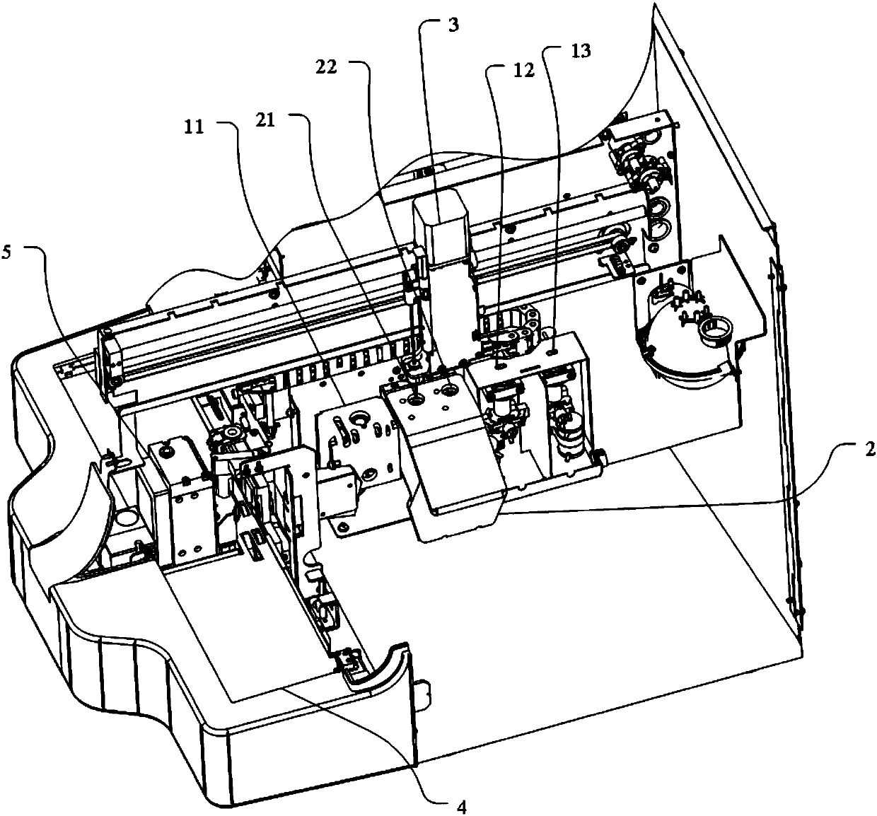
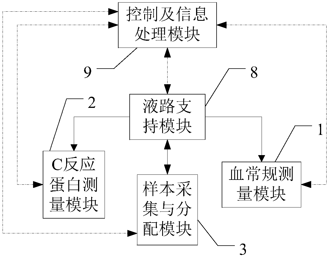
[0036] Please refer to figure 1 and figure 2 , is a structure of the blood testing instrument disclosed in this embodiment. in, figure 1 It is a schematic diagram of the three-dimensional structure of the blood detector, figure 2 It is a block diagram of the structure and principle of the blood detector; figure 2 The dotted arrow line in the figure is the direction of the electrical signal, and the solid arrow line is the direction of the liquid circuit. The blood tester includes: routine blood measurement module 1 ( figure 1Not shown in the marker), C-reactive protein measurement module (hereinafter also referred to as CRP measurement module) 2, sample collection and distribution module 3, liquid circuit support module 8 ( figure 1 Not shown in the mark) and the control and information processing module 9 ( figure 1 not shown). in:
[0037] The routine blood measurement module 1 is used to provide a measurement place for the allocated samples, measure the allocated...
Embodiment 2
[0063] The difference between this embodiment and the above-mentioned embodiments is that the blood detector disclosed in this embodiment also includes an automatic sampling module 4, such as figure 1 As shown, the automatic sampling module 4 provides continuous samples for the sample collection and distribution module 3 and completes sample loading and unloading. The automatic sampling module 4 is preferably arranged at the front end of the blood tester. Please refer to Figure 7 , is a top view diagram of the automatic sampling module, mainly including: a test tube rack conveying mechanism 41, a loading position detection mechanism 42, a test tube rack loading mechanism 43, a test tube rack unloading mechanism 44, a test tube presence detection mechanism 45 and a test tube barcode information acquisition mechanism 46. The working process is as follows: the test tube rack conveying part 41 transports the test tube rack with placed test tubes to the loading area 410 along the ...
Embodiment 3
[0076] The difference between this embodiment and the above-mentioned embodiment is that the blood detector disclosed in this embodiment also includes a latex reagent storage module 5, such as figure 1 As shown, the latex reagent storage module 5 is used to provide a low-temperature storage environment for the latex reagent, and the latex reagent storage module 5 is arranged in a position of the blood detector closer to the edge of the detector and away from the inside. The advantage of setting the latex reagent storage module 5 away from the inside of the detector is that it not only facilitates the replacement of latex reagents, but also prevents users from putting their hands into the inside of the instrument when replacing latex reagents, reducing the risk of biological contamination for users.
[0077] In the preferred embodiment, please refer to Figure 7 , the latex reagent storage module 5 can be arranged between the sample loading area 410 and the sample unloading are...
PUM
 Abstract
Description
Claims
Application Information