Return path via hole viewing method and system

A technology of return path and via hole, which is applied in the field of return path via hole inspection method and system, and can solve time-consuming and other problems

Active Publication Date: 2018-02-02
ZHENGZHOU YUNHAI INFORMATION TECH CO LTD
View PDF7 Cites 1 Cited by
  • Summary
  • Abstract
  • Description
  • Claims
  • Application Information

AI Technical Summary

Problems solved by technology

However, any PCB board has many vias, so this method is very time-consuming

Method used


Image

  • Return path via hole viewing method and system
  • Return path via hole viewing method and system
  • Return path via hole viewing method and system

Examples


Embodiment Construction

[0049] The following will clearly and completely describe the technical solutions in the embodiments of the present invention with reference to the accompanying drawings in the embodiments of the present invention. Obviously, the described embodiments are only some, not all, embodiments of the present invention. Based on the embodiments of the present invention, all other embodiments obtained by persons of ordinary skill in the art without making creative efforts belong to the protection scope of the present invention.

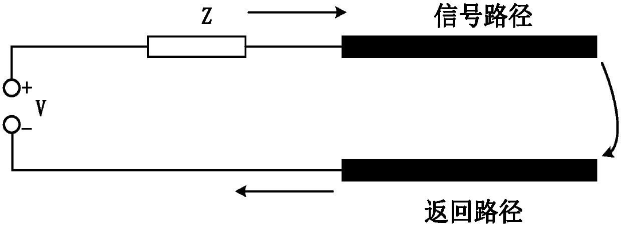
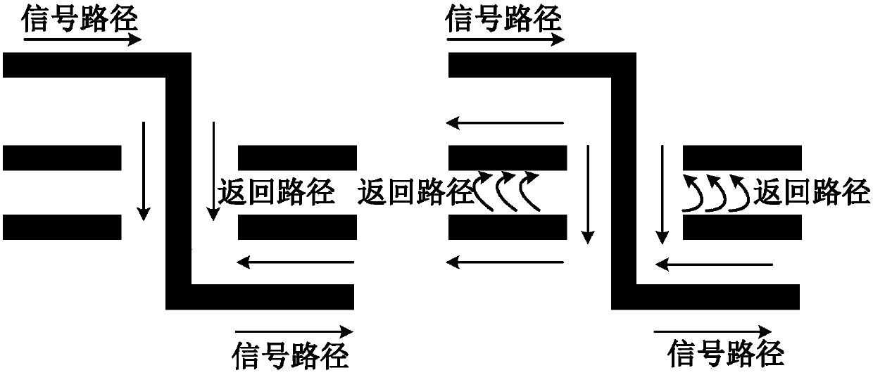
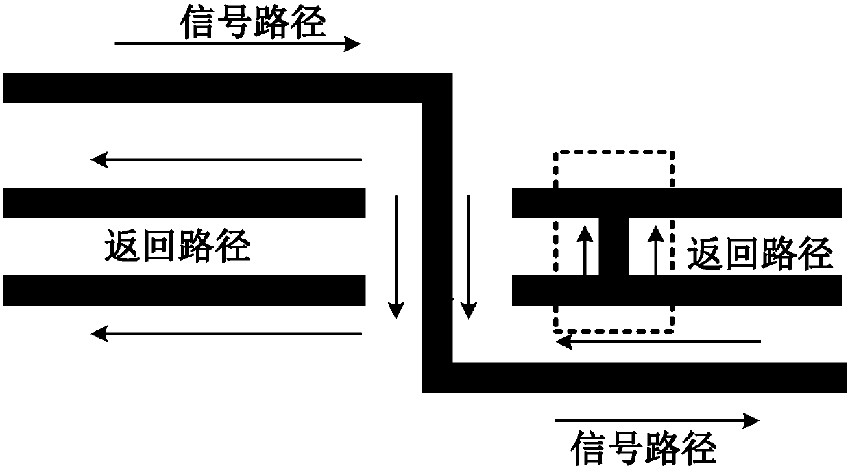
[0050] The embodiment of the present invention discloses a return path via inspection method, see Figure 4 The flowchart shown includes:

[0051] Step S11: Identify all signal vias and return path vias in the target PCB.

[0052] It should be noted that there are tens of thousands of vias in the target PCB, and it is impossible to accurately identify the signal vias and return path vias with the naked eye. Therefore, the present invention identifies all sig...


PUM


Abstract

The application discloses a return path via hole viewing method and system. The method comprises the steps of: identifying all signal via holes and return path via holes in a target PCB; respectivelycalculating distances between each signal via hole and all the return path via holes to obtain corresponding N groups of distances, wherein the value of N is consistent with the number of the signal via holes in the target PCB; respectively determining out a corresponding distance with the minimum distance value from each group of distances so as to obtain corresponding N shortest distances; respectively determining whether each shortest distance is smaller than a preset distance threshold; if yes, determining that the return path via holes corresponding to the shortest distances accord with the layout standard; and if no, determining that the return path via holes corresponding to the shortest distances do not accord with the layout standard. According to the application, the shortest distances between the signal via holes and the return path via holes are calculated by utilizing common computational software of a computer so as to determine whether the return path via holes accord with the layout standard, thereby greatly shortening viewing time of the signal path via holes.

Description

technical field [0001] The invention relates to the field of circuits, in particular to a method and system for inspecting return path vias. Background technique [0002] A transmission line for a signal carries the signal from one end to the other. All transmission lines are composed of two paths, one of which is called the signal path, and the other is called the return path, such as figure 1 shown. In the four-layer circuit transmission line, such as figure 2 As shown, the first layer circuit and the fourth layer circuit are the signal layer, and the second layer circuit and the third layer circuit are the GND layer, that is, the reference plane. Such as figure 2 As shown in the transmission direction of the signal in , the signal path starts from the first layer circuit and connects to the fourth layer circuit through the signal via. The return current will switch from the third layer circuit back to the second layer circuit. At this time, the return path is disc...

Claims


Application Information

Patent Timeline
Patent Type & Authority Applications(China)
IPC IPC(8): G06F17/50
CPCG06F30/392
Inventor 陈麒旭
Owner ZHENGZHOU YUNHAI INFORMATION TECH CO LTD
Why Eureka
Try Eureka