Accumulation imaging

a technology of accumulation imaging and ultrasound imaging, which is applied in the field of ultrasound imaging of anatomical structures, can solve the problems of reducing the overall pixel to pixel reducing the quality of the combined image, and reducing the image quality, so as to improve the display of ultrasound imaging, enhance diagnosis, and reduce the number of image frames in the set of n image frames

Active Publication Date: 2006-02-23
GENERAL ELECTRIC CO
View PDF7 Cites 2 Cited by
  • Summary
  • Abstract
  • Description
  • Claims
  • Application Information

AI Technical Summary

Benefits of technology

[0010] A preferred embodiment of the present invention provides a system for improving the display of ultrasound imaging of tissue structures. A set of N image frames is used to produce a peak image display. Multiple peak image displays are produced by discarding the oldest image frame in the set of N image frames and replacing the discarded image frame with another more recent image frame. The more recent image frame is added to the set of image frames to produce a new set of N image frames. The new set of N image frames is used to produce another peak display image. If there is an undesirable amount of distortion or blur in the peak display images due to tissue motion, then the number of image frames in the set of N image frames can be reduced.
[0011] To enhance diagnosis and reduce viewing time, peak display images can be displayed in a split screen mode with other ultrasound images. For example, a peak display image can be displayed in a first portion of the monitor while a real time image is displayed in a second portion of the monitor. Using the split screen mode in this manner allows a medical technician to see a contrast agent as it is flowing through a patient alongside an image that shows the path traveled by the contrast agent.

Problems solved by technology

Combining data from successive image frames where corresponding tissue structures are misaligned blurs the boundaries between tissue structures and reduces the overall quality of the combined image.
Because the corresponding tissue structures are represented by different pixels in successive image frames, comparing and combining images with misaligned tissue structures pixel to pixel reduces the quality of the combined image.
The quality of the image is reduced because misaligned tissue structures in images being compared can result in pixels for body anatomy such as a vein being compared with pixels for a strong reflector such as a tendon resulting in peak values for the tendon possibly replacing values for the vein in the peak display image.
Consequently, such misalignment of corresponding tissue structures in successive image frames can blur the boundaries between tissue structures, such as the vein and the tendon, in the peak display image.
As a result, prior art systems are susceptible to motion artifacts and blurring because a significant amount of tissue motion can occur during the course of an entire ultrasound procedure.
While an example using contrast agent imaging and a peak display image has been presented, misalignment of corresponding tissue structures is a problem for other ultrasound imaging modes as well.
Due to the sheer number of pixels, comparisons, and correlations, re-aligning corresponding tissue structures using spatial correlation measures requires substantial time and software processing.
Delays in image processing due to processing time reduce patient throughput and waste valuable technician time.

Method used


Image

  • Accumulation imaging
  • Accumulation imaging
  • Accumulation imaging

Examples


Embodiment Construction

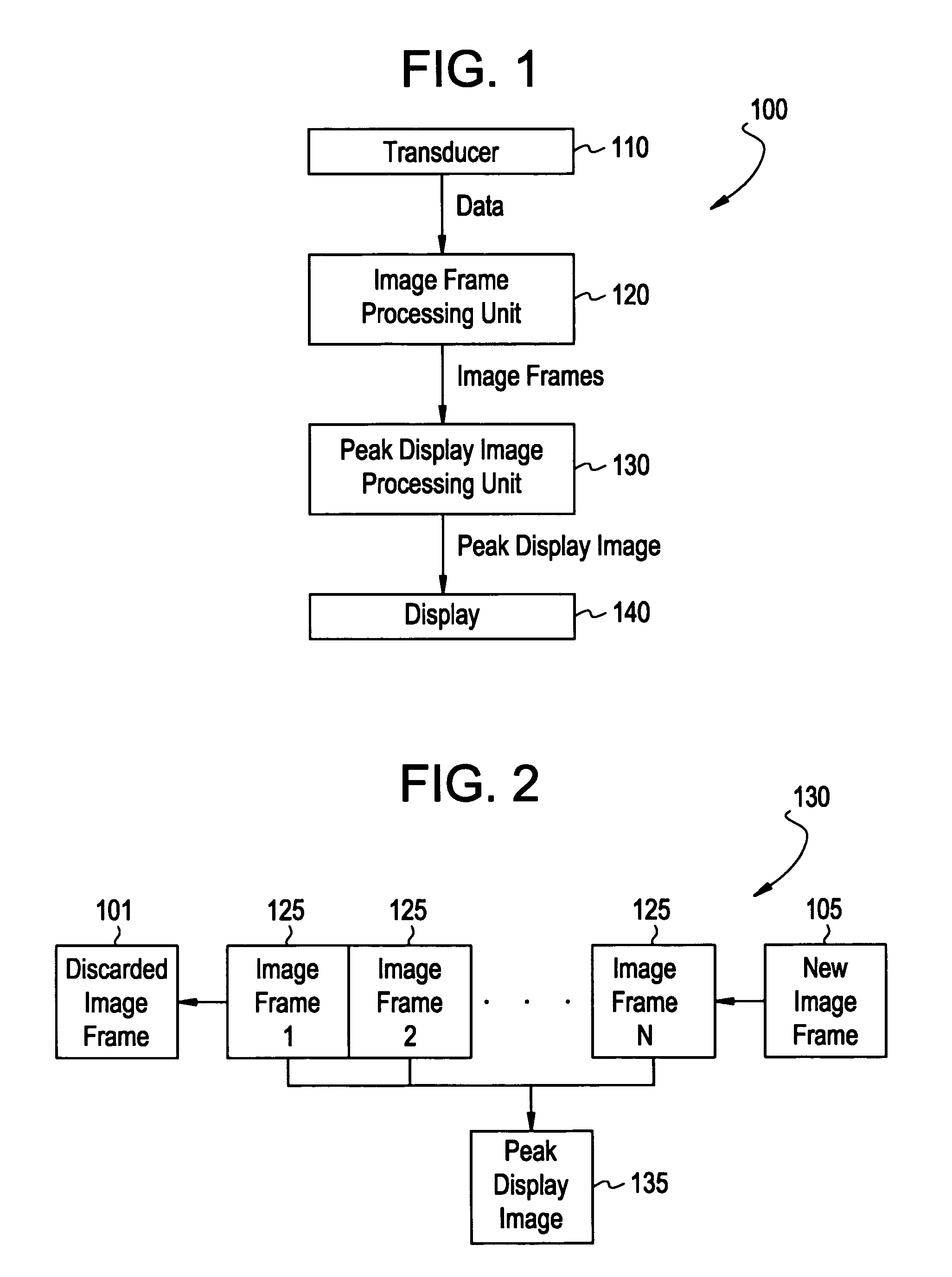
[0016]FIG. 1 illustrates a system 100 for reducing the effects of tissue motion on a peak display image in accordance with an embodiment of the present invention. The system 100 includes a transducer 110, an image frame processing unit 120, a peak display image processing unit 130, and a display 140. The transducer 110 transmits data to the image frame processing unit 120. The image frame processing unit 120 processes the data into ultrasound image frames and transmits the image frames to the peak display image processing unit 130. The peak display image processing unit 130 processes the image frames into a peak display image and transmits the peak display image to the display 140. The display 140 displays the peak display image on a monitor.

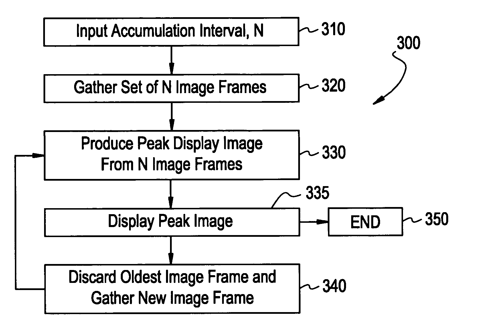
[0017]FIG. 2 is a block diagram that illustrates operation of the peak display image processing unit 130 of FIG. 1 in accordance with an embodiment of the present invention. The peak display image processing unit 130 receives a predetermined nu...


PUM


Abstract

A system for improving the display of ultrasound imaging of tissue structures. A set of N image frames is used to produce a peak image display. Multiple peak image displays are produced by discarding the oldest image frame in the set of N image frames and replacing the discarded image frame with another more recent image frame. The more recent image frame is added to the set of image frames to produce a new set of N image frames. The new set of N image frames is used to produce another peak display image. If there is an undesirable amount of distortion or blur in the peak display images due to tissue motion, then the number of image frames in the set of N image frames can be reduced.

Description

BACKGROUND OF THE INVENTION [0001] The present invention generally relates to ultrasound imaging of anatomical structures. In particular, the invention relates to a method and system for improving the display of ultrasound imaging of anatomical structures. [0002] For a number of years, ultrasound imaging has been used to non-invasively monitor and image anatomical structures within the human body. To produce the image, an ultrasonic transducer transmits an ultrasonic wave of energy into a patient's body. The properties of ultrasonic echoes returning from various structures and elements within the patient's body are then used to produce frames of data referred to as image frames. As the image frames are acquired, they may be displayed on a monitor, output to a printer, and / or stored in a memory for playback at a later time. [0003] The human body is not an immobile object. Patient's breathe, blood flows, and tissues move. Because tissues within the patient move during the course of an...

Claims


Application Information

Patent Timeline
Patent Type & Authority Applications(United States)
IPC IPC(8): G06K9/00
CPCA61B8/5276A61B8/08
Inventor HALL, ANNE LINDSAYWASHBURN, MICHAEL JOSEPHMIYAMA, KOJILACONTE, KIRSTIN NORA
Owner GENERAL ELECTRIC CO
Why Eureka
Try Eureka