External inserting type funnel

A technology of funnel and funnel tube, which is applied in the field of household dumping, and can solve problems such as difficult flow of large granular objects

Pending Publication Date: 2018-02-06
闫泰来
View PDF5 Cites 0 Cited by
  • Summary
  • Abstract
  • Description
  • Claims
  • Application Information

AI Technical Summary

Problems solved by technology

[0005] The purpose of the present invention is to provide an externally inserted funnel to solve the problem that the existing funnel is not easy to flow large granular objects

Method used


Image

  • External inserting type funnel
  • External inserting type funnel
  • External inserting type funnel

Examples


Embodiment 1

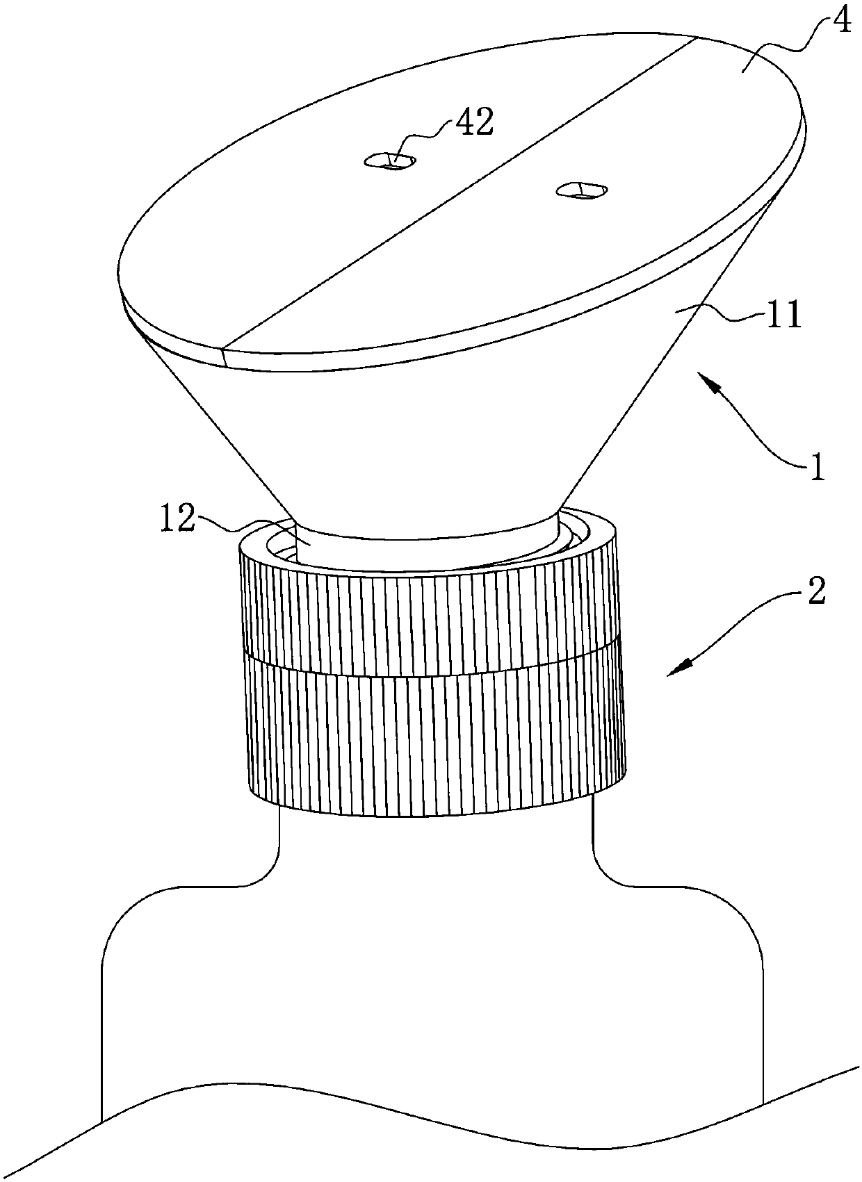
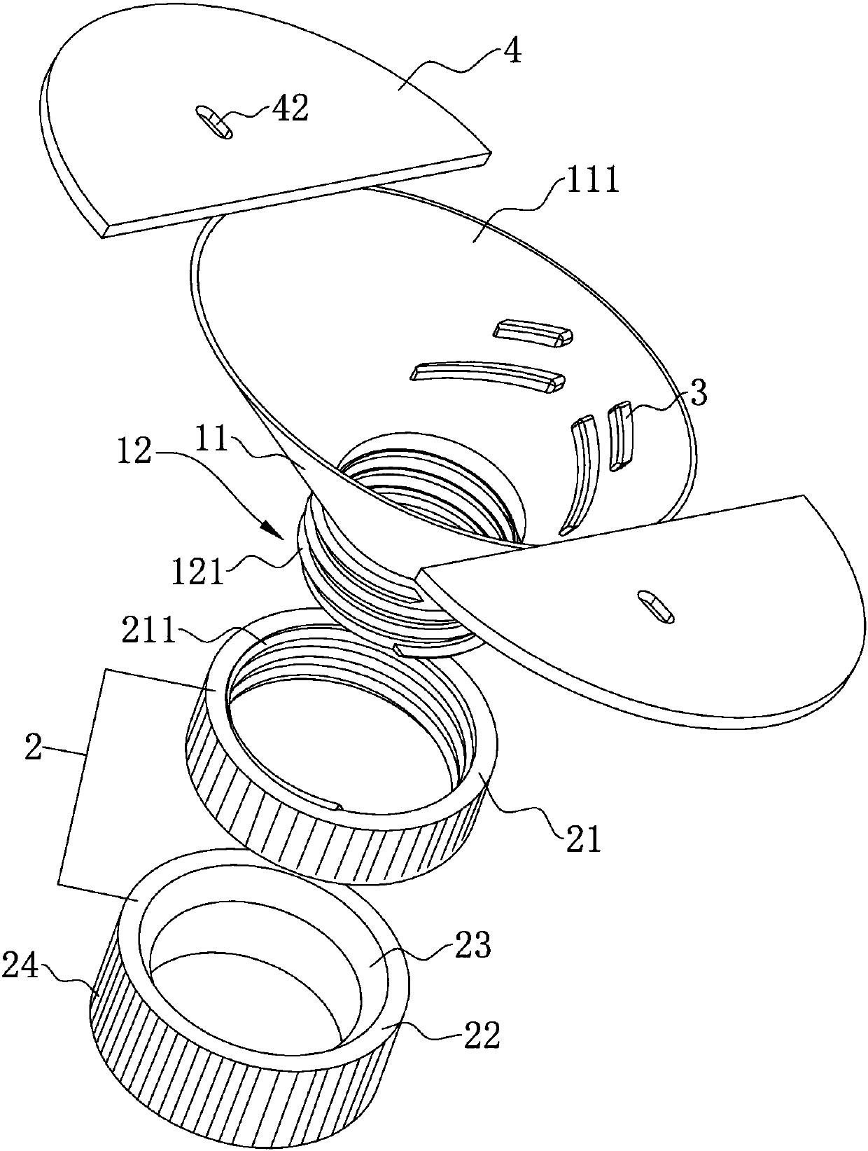
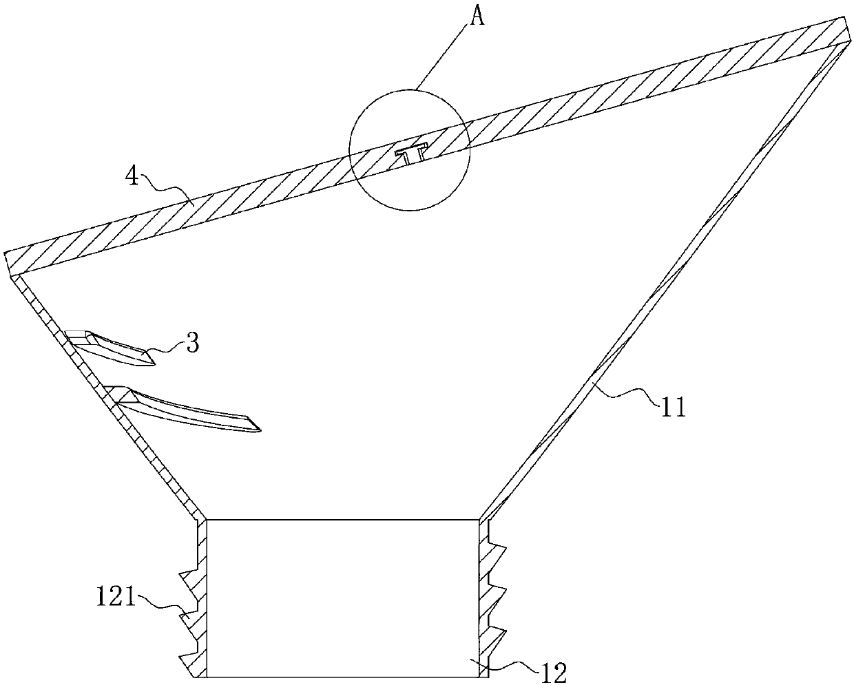
[0032] Such as figure 1 with figure 2 As shown, the present invention provides an externally inserted funnel, which includes a funnel body 1 and a funnel connector 2 installed on the funnel body 1 . The funnel body 1 includes a funnel tube 11 and a funnel tube 12 integrally formed at the bottom of the funnel tube 11. The upper port of the funnel tube 11 forms a feed inlet 111 along an inclined surface. The funnel tube 12 is cylindrical, and the length of the funnel tube 12 is less than The length of the funnel barrel 11, the funnel connector 2 is fitted on the funnel tube 12, and the end of the funnel connector 2 away from the funnel tube 11 is fitted on the container mouth, and the funnel body 1 is fixed by the external plug-in installation of the funnel connector 2 On the mouth of the container, the space for the flow of poured objects in the funnel tube 12 is increased to facilitate the flow of large particle objects from the funnel body 1 into the container. In order to...

Embodiment 2

[0039] Such as Figure 5 As shown, the difference from Embodiment 1 is that the upper connector 21 and the lower connector 22 are cylindrical, and the inner diameter of the upper connector 21 is smaller than the inner diameter of the lower connector 22, and the upper connector 21 and the lower connector 22 The connection of the funnel body 1 forms a boss shape in the funnel connector 2, and the funnel body 1 and the container are installed in the upper connector 21 and the lower connector 22 respectively, so that the funnel body 1 can be installed outside the funnel pipe 12 with a diameter larger than that of the funnel. diameter container.

Embodiment 3

[0041] Such as Image 6 As shown, the difference from Embodiment 1 is that the upper connector 21 and the lower connector 22 are cylindrical, and the inner diameter of the upper connector 21 is greater than the inner diameter of the lower connector 22, and the upper connector 21 and the lower connector 22 The connection of the funnel body 1 forms a boss shape in the funnel connector 2. By fitting the funnel body 1 and the container in the upper connector 21 and the lower connector 22 respectively, it is convenient to install the funnel body 1 where the caliber is smaller than the inner diameter of the funnel tube 12. container.

[0042] In the externally inserted funnel of the present invention, the funnel tube is designed to be cylindrical, and the corresponding funnel connectors are installed in conjunction with it, and different funnel connectors are installed on the corresponding container mouths in an externally inserted manner to increase the amount of pouring in the fun...


PUM


Abstract

The invention discloses an external inserting type funnel. The external inserting type funnel comprises a funnel body and a funnel connecting part which is mounted on the funnel body, wherein the funnel body comprises a funnel barrel and a funnel pipe which is internally molded at the bottom end of the funnel barrel; an upper end opening of the funnel barrel forms a feeding opening along an inclined plane; a plurality of deceleration strips are arranged on an inner wall, which is located at one relatively low side of the feeding opening, of the funnel barrel; the funnel pipe is cylindrical; afirst thread buckle is opened on the outer wall of the funnel pipe; the funnel connecting part comprises an upper connecting part, a lower connecting part and an anti-sticking part; a second thread buckle is opened on an inner wall of the upper connecting part; the funnel connecting part is fixed on the funnel pipe by screwing the first thread buckle into the second thread buckle; the anti-sticking part is arranged on the inner wall of the lower connecting part in a surrounding manner and a dust baffle plate capable of being opened and closed is mounted at the feeding opening. According to theexternal inserting type funnel disclosed by the invention, a flowing space of a poured material in the funnel pipe is increased, so that large-size particulate matters are convenient to flow in the funnel.

Description

technical field [0001] The invention relates to the technical field of domestic pouring, in particular to an externally inserted funnel. Background technique [0002] In daily life, it is often necessary to dump some specific objects from one container to another for storage or use, and the containers used to hold objects are generally small-caliber containers. In order to facilitate the dumping of objects, it is necessary to add A funnel makes it easier to pour objects into containers. [0003] Existing funnels are all plug-in funnels, and the funnel mouth is generally a flat mouth. The funnel tube is inserted into the container along the container mouth of the container, and then the object is poured into the funnel, and the object is transported into the container through the funnel. [0004] However, because the above-mentioned funnel is an insert type, the end port of the funnel tube is slender, and large granular objects are not easy to flow into the container. Cont...

Claims


Application Information

Patent Timeline
Patent Type & Authority Applications(China)
IPC IPC(8): B67C11/00
CPCB67C11/00
Inventor 闫泰来
Owner 闫泰来
Why Eureka
Try Eureka