
Mobile power supply storage device and mobile power supply renting device

A mobile power supply and storage device technology, applied in the direction of circuit devices, battery circuit devices, coupling devices, etc., can solve problems affecting user experience, charging failure, etc.

Pending Publication Date: 2018-02-06
深圳市车望神州科技有限公司
View PDF0 Cites 8 Cited by
  • Summary
  • Abstract
  • Description
  • Claims
  • Application Information

AI Technical Summary

Problems solved by technology

[0003] The mobile power supply rental equipment includes a mobile power storage device, but the current mobile power storage device relies on the user to correctly place the mobile power supply in the mobile power storage device when the user returns the mobile power supply, so that the charging contacts of the mobile power supply and the mobile power storage device Only when the charging thimble is in contact can the mobile power supply be charged. However, when the mobile power supply is placed, the charging contact of the mobile power supply may not be in contact with the charging thimble of the mobile power supply storage device, resulting in charging failure and affecting user experience.

Method used


Image

  • Mobile power supply storage device and mobile power supply renting device
  • Mobile power supply storage device and mobile power supply renting device
  • Mobile power supply storage device and mobile power supply renting device

Examples


Embodiment Construction

[0035] The following will clearly and completely describe the technical solutions in the embodiments of the present invention with reference to the drawings in the embodiments of the present invention.

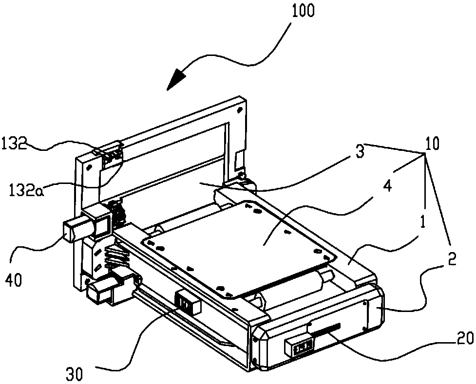
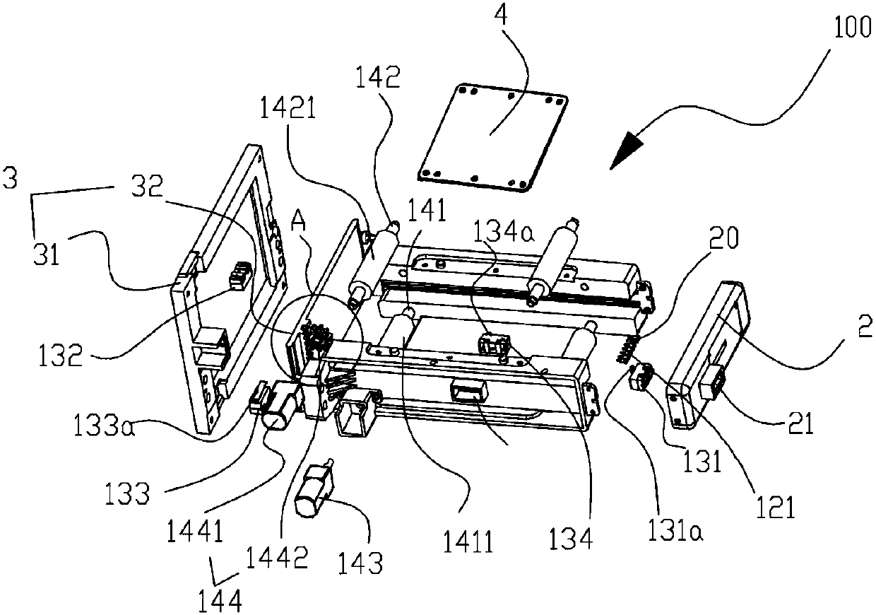
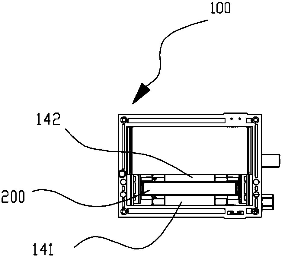
[0036] see Figure 1 to Figure 6, the present invention provides a mobile power storage device 100, wherein the mobile power storage device 100 includes a storage bin 10, a charging assembly 20, a detection assembly 30, and a transmission assembly 40, and the storage bin 10 includes two oppositely arranged guide rails 1. The rear cover 2, the guide rail 1 is used to slide and guide the mobile power supply 200, the rear cover 2 is fixedly connected between the two guide rails 1, and is located at one end of the two guide rails 1; the charging The assembly 20 includes a charging thimble 121 , the detection assembly 30 includes a first sensor 131 , the charging thimble 121 and the first sensor 131 are fixed side by side on the rear cover 2 , and the charging thimble 121 is used f...


PUM


Abstract

The invention discloses a mobile power supply storage device and a mobile power supply renting device. The structure of the mobile power source storage device is as follows: a storage bin comprises two guide rails and a rear cover, wherein the two guide rails are oppositely arranged. The guide rails are used for guiding the sliding of a mobile power supply. The rear cover is fixedly connected between the two guide rails and is located at one end of the two guide rails. A charging ejector pin and a first sensor are fixed on the rear cover side by side. A first rotating shaft and a second rotating shaft are respectively and rotationally connected between the two guide rails. The first rotating shaft is parallel to the second rotating shaft, and the first rotating shaft and the second rotating shaft are perpendicular to the guide rails. The outer peripheral side wall of the first rotating shaft and the outer peripheral side wall of the second rotating shaft are respectively in rolling cooperation with the two opposite sides of the mobile power supply. A first motor is fixed on the guide rails, and the first motor is rotationally connected with the first rotating shaft. The first motoris used for driving the first rotating shaft to rotate so as to drive the mobile power supply to move along the guide rails. When the first sensor detects that the mobile power supply abuts against the charging ejector pin, the first motor stops rotating.

Description

technical field [0001] The invention relates to the technical field of mobile power charging, in particular to a mobile power storage device and mobile power rental equipment. Background technique [0002] With the development of science and technology, the hardware and software of smartphones are becoming more and more powerful. People can use smartphones to handle various aspects of affairs such as family, work, and social interaction. The time people use smartphones continues to increase, causing smartphones to easily run out , using mobile power as a backup power supply to charge smartphones has become a common choice for most people. At present, there have been mobile power rental equipment that can rent mobile power for those who need it. [0003] The mobile power supply rental equipment includes a mobile power storage device, but the current mobile power storage device relies on the user to correctly place the mobile power supply in the mobile power storage device whe...

Claims


Application Information

Patent Timeline
IPC IPC(8): H02J7/00H01R13/641H01R13/66
CPCH01R13/641H01R13/6683H02J7/0044H02J7/0045
Inventor 张文明
Owner 深圳市车望神州科技有限公司
Learn More