Direct-current resistance spot-welding multi-mode feedback control method

A DC resistance and feedback control technology, applied in resistance welding equipment, welding monitoring devices, welding power sources, etc., can solve the problem of inability to compensate for the impact, and achieve the effect of saving adjustment time, improving the quality of solder joints, and suppressing spatter

Active Publication Date: 2018-02-09
SHANGHAI JIAO TONG UNIV
View PDF7 Cites 11 Cited by
  • Summary
  • Abstract
  • Description
  • Claims
  • Application Information

AI Technical Summary

Problems solved by technology

[0003] The present invention aims at the deficiencies of the current resistance spot welding technology that mostly adopts fixed current waveform or fixed heat balance factor in the heating process control, which cannot compensate the influence of abnormal welding conditions on the welding process, etc., and proposes a DC resistance spot welding multi-mode feedback control method, which controls the quality of solder joints and the welding process in real time, significantly improves the quality of solder joints at key stations, effectively suppresses spatter in the welding process, improves the stability of welding quality, and saves a lot of time for adjusting process parameters for different working conditions

Method used


Image

  • Direct-current resistance spot-welding multi-mode feedback control method
  • Direct-current resistance spot-welding multi-mode feedback control method
  • Direct-current resistance spot-welding multi-mode feedback control method

Examples


Embodiment Construction

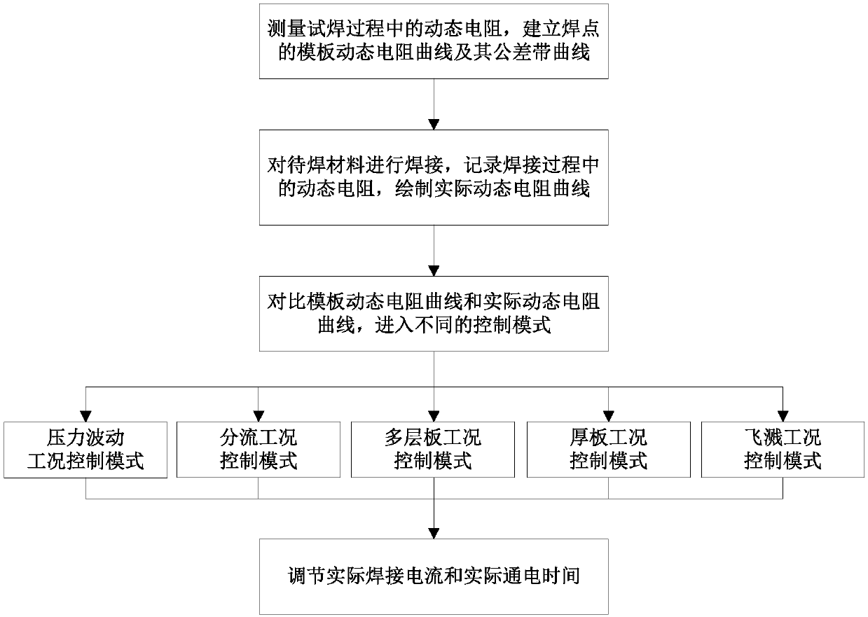
[0050] Such as figure 1 As shown, this embodiment specifically includes the following steps:

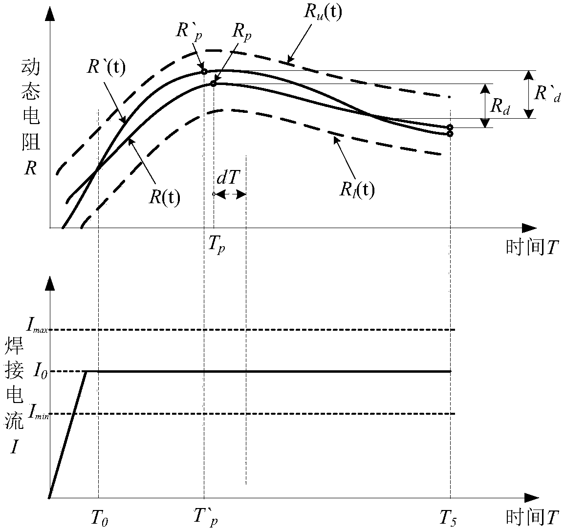
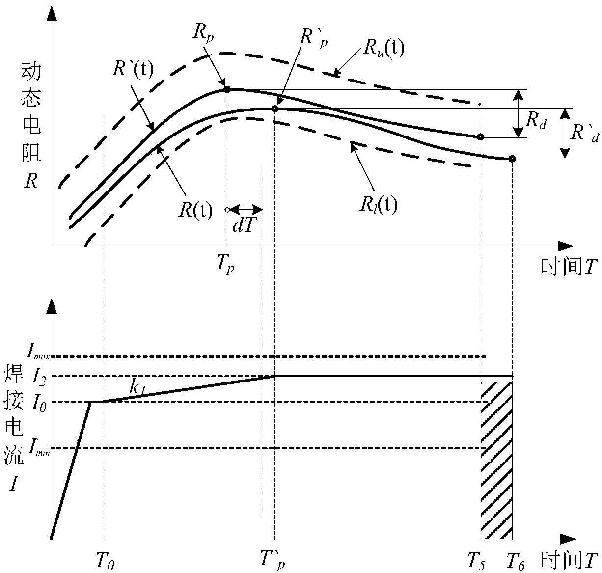
[0051] 1) Test welding is carried out under standard welding conditions, and the welding current is I 0 , measure the dynamic resistance during the test welding process, establish the template dynamic resistance curve R(t) of the solder joint, and its upper tolerance zone curve R u (t) and lower tolerance zone curve R l (t), the template dynamic resistance curve peak value is R p , R p The corresponding moment is T p , the drop of template dynamic resistance curve after the peak value is R d , the maximum power-on time is T 5 .

[0052] 2) The material to be welded is welded, and the initial welding current is I 0 , measure the dynamic resistance during the actual welding process, draw the actual dynamic resistance curve R′(t), and the peak value of the actual dynamic resistance curve is R′ p , R' p The corresponding moment is T′ p , the actual dynamic resistance curve dro...


PUM


Abstract

The invention relates to a direct-current resistance spot-welding multi-mode feedback control method, which comprises the steps of (1) carrying out test weld under a standard welding condition, wherein a welding current magnitude is I0; and building a template dynamic resistance curve R (t), an upper tolerance zone curve Ru (t) and a lower tolerance zone curve R1 (t) of a welding spot, wherein a peak value of the template dynamic resistance curve is Rp, the moment corresponding to the Rp is Tp, the declining volume of the template dynamic resistance curve after the peak value is Rd, and the maximum conduction time is T5; (2) welding a material to be welded, wherein an initial welding current magnitude is I0; and drawing an actual dynamic resistance curve R' (t), wherein a peak value of theactual dynamic resistance curve is R'p, the moment corresponding to the R'p is T'p, and the declining volume of the actual dynamic resistance curve after the peak value is R'd; and (3) entering different control modes, and dynamically adjusting an actual welding current and actual conduction time. According to the direct-current resistance spot-welding multi-mode feedback control method providedby the invention, the welding spot quality and a welding process are controlled in real time, the welding spot quality of a key station is remarkably improved, the spattering during the welding process is effectively inhibited, the stability of the welding quality is improved, and a lot of technological parameter adjusting time aiming at different working conditions is saved.

Description

technical field [0001] The invention relates to a technology in the field of welding, in particular to a multi-mode feedback control method for DC resistance spot welding. Background technique [0002] The spot welding process is a highly nonlinear process with multi-variable coupling effects and a large number of random uncertain factors. The heat input of spot welding and the formation of nugget nuggets are related to many process parameters, including welding current, welding time, electrode pressure, Electrode material and its end face size, workpiece configuration, weldment material combination, and workpiece surface coating coating status, etc. Therefore, in the welding process, it is often necessary to determine the appropriate process parameters according to the above-mentioned changes in the working conditions in order to achieve an excellent welding effect. This process relies heavily on the experience of the operator, and usually requires multiple attempts to ach...

Claims


Application Information

Patent Timeline
Patent Type & Authority Applications(China)
IPC IPC(8): B23K11/11B23K11/24B23K11/25
Inventor 夏裕俊楼铭李永兵
Owner SHANGHAI JIAO TONG UNIV
Why Eureka
Try Eureka