Bulk cargo self-discharging carriage

A cargo and self-unloading technology, applied in the direction of vehicles with a chain/ring belt, etc., can solve problems such as complex structure, and achieve the effect of simple structure, good economy and convenience

Inactive Publication Date: 2018-02-09
王东文
View PDF1 Cites 3 Cited by
  • Summary
  • Abstract
  • Description
  • Claims
  • Application Information

AI Technical Summary

Problems solved by technology

However, the bottom plate of this invention is designed as two movable bottom plates, and the structure is relatively complicated.

Method used


Image

  • Bulk cargo self-discharging carriage
  • Bulk cargo self-discharging carriage
  • Bulk cargo self-discharging carriage

Examples


Embodiment Construction

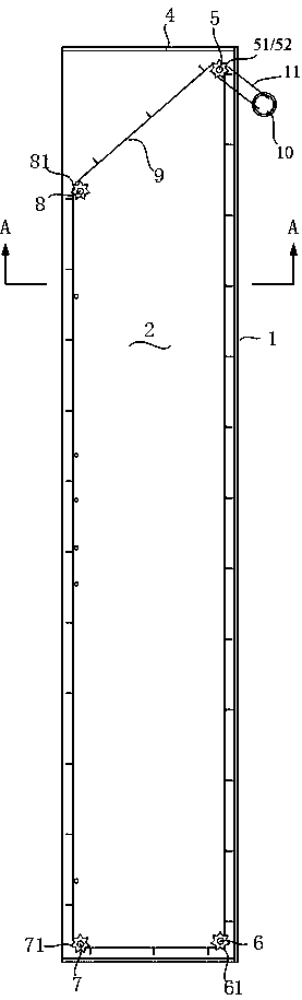
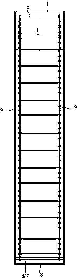
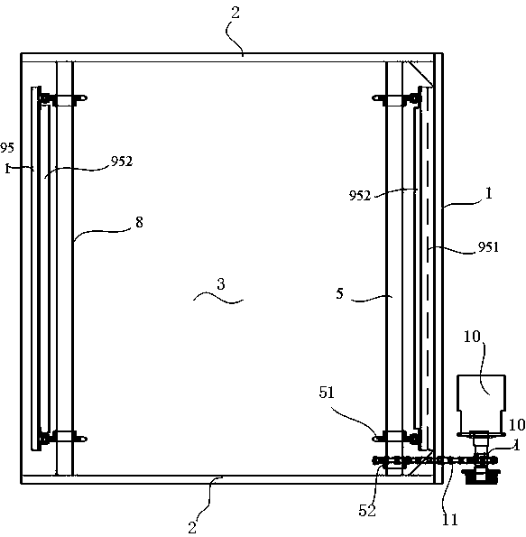
[0013] Refer to attached Figure 1-4 . A bulk cargo dump car, comprising a bottom plate 1, side plates 2 on both sides fixed to the bottom plate, a front plate 3 fixed to the front ends of the bottom plate and side plates, and abutted against the rear ends of the bottom plate and side plates Or separated rear door 4, near the top of the base plate, near the rear door, pivotally set the drive shaft 5 with the side plates 2 on both sides as bearings, and pivotally set the side plates on both sides as bearings near the top of the bottom plate, near the front plate. The first driven shaft 6 of the bearing, the second driven shaft 7 with the two side plates as bearings is pivoted near the upper ends of the two side plates and the front plate, and the second driven shaft 7 is pivoted near the upper ends of the two side plates, Near the rear door, a third driven shaft 8 with two side plates as bearings is pivoted; the projections of the first driven shaft 6 and the second driven sha...


PUM


Abstract

The invention discloses a bulk cargo self-unloading compartment. After a hydraulic motor is started, the unloading chain is driven to rotate counterclockwise through a drive chain, and the scraper on the unloading chain gradually drags the bulk cargo out of the compartment. Compared with the prior art, the present invention has a simple structure, does not need to set a movable floor at the bottom of the carriage, has better economy and convenience, and can be applied not only to new carriages, but also to the transformation of existing carriages.

Description

technical field [0001] The invention relates to a transportation equipment, in particular to a dump truck for bulk cargo. Background technique [0002] At present, grain circulation is gradually developing towards bulk transportation. Usually, the grain storage area is equipped with conveying equipment for loading grain, but there is no corresponding equipment at the grain unloading area to unload bulk goods such as grain from the compartment. [0003] The utility model patent with the publication number CN201193006Y discloses a vehicle-mounted conveyor belt unloading type bulk grain transport vehicle. The bottom plate of the sealed box is designed as two movable bottom plates, and the outer side of each movable bottom plate is connected with a movable bottom plate sealing strip, which is in contact with the inner side of the sealed box. The lifting cylinder is connected, and the floor lifting cylinder is connected with the chassis through the pin shaft of the floor liftin...

Claims


Application Information

Patent Timeline
IPC IPC(8): B60P1/38
CPCB60P1/38
Inventor 王东文郭章超李美燕高淑芬王超
Owner 王东文
Why Eureka
Try Eureka