
Universal appliance tooling for vehicle top luggage rack

A luggage rack and appliance technology, which is applied in the field of auto parts, can solve the problems of resource waste, old-fashioned appliance trolleys cannot meet the requirements of the luggage rack aging process, and items cannot be used universally, and achieve the effect of reducing investment or waste

Pending Publication Date: 2018-02-09
MINTH AUTOMOTIVE TECH RES & DEV CO LTD
View PDF7 Cites 1 Cited by
  • Summary
  • Abstract
  • Description
  • Claims
  • Application Information

AI Technical Summary

Problems solved by technology

[0002] At present, there are many luggage rack tools and tools in the auto parts factory. The specifications are not uniform. Each project development must design a special tool and tool, which cannot be used in common with other projects. At present, the tools and tools are not enough or the tools and tools are purchased many times during the development of many projects. After the completion of the project development, the background car will be scrapped, resulting in a lot of waste of resources. The old-fashioned appliance trolley cannot meet the requirements of the luggage rack aging process, and the trolley cannot meet the high temperature of 2800-3500 without melting. Adverse effects, etc., the luggage rack is an exterior decoration that has high requirements on the appearance of the product, so the equipment must meet the protection of the appearance of the luggage rack, and can meet the requirements of different processes, so it is urgent to design a product that can make different Luggage racks can be used universally and meet the requirements of different processes.

Method used


Image

  • Universal appliance tooling for vehicle top luggage rack
  • Universal appliance tooling for vehicle top luggage rack
  • Universal appliance tooling for vehicle top luggage rack

Examples


Embodiment Construction

[0019] The following are specific embodiments of the present invention and in conjunction with the accompanying drawings, the technical solutions of the present invention are further described, but the present invention is not limited to these embodiments.

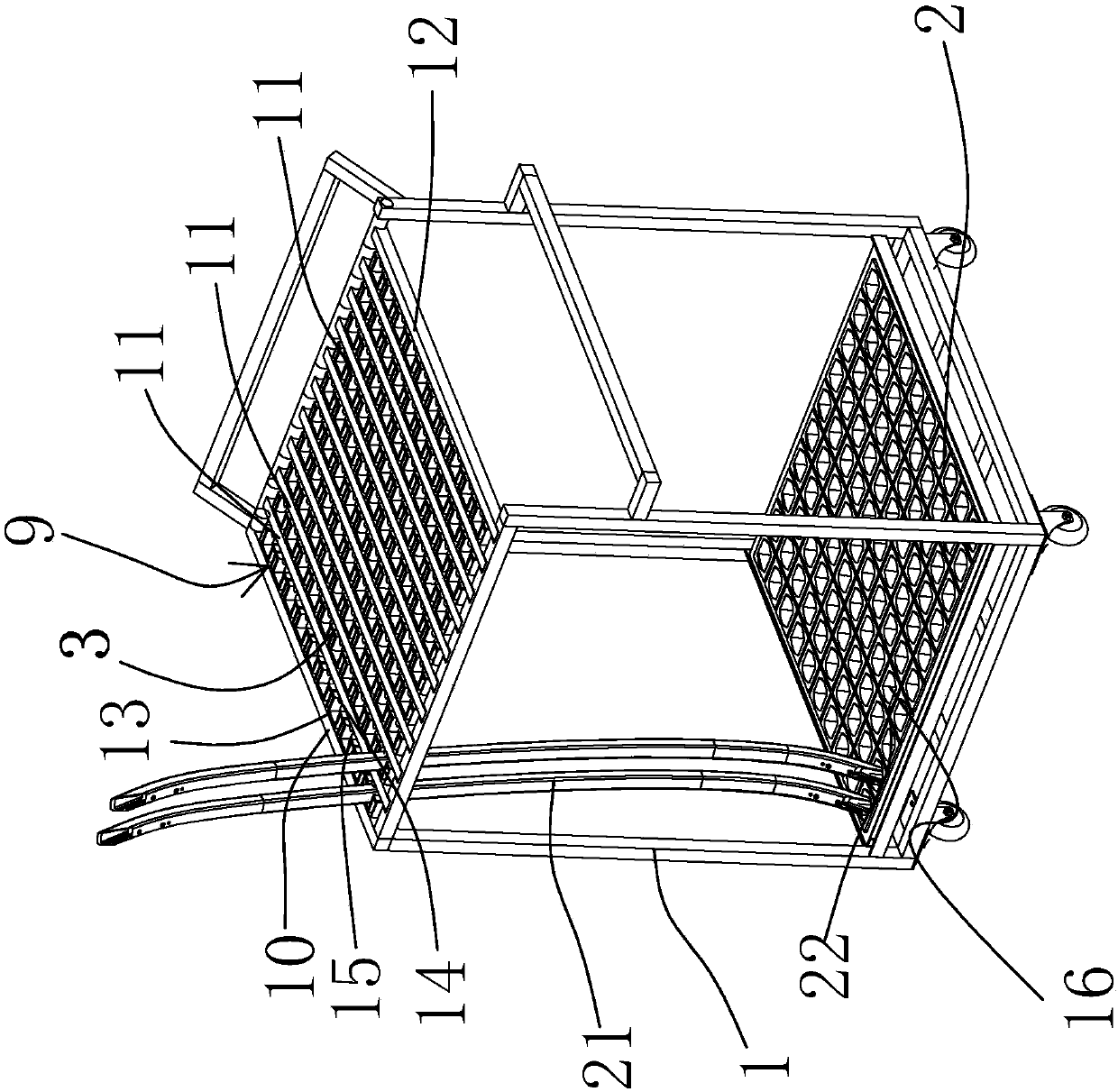
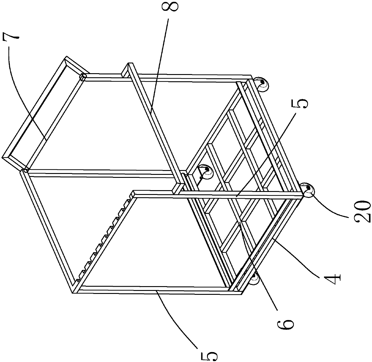
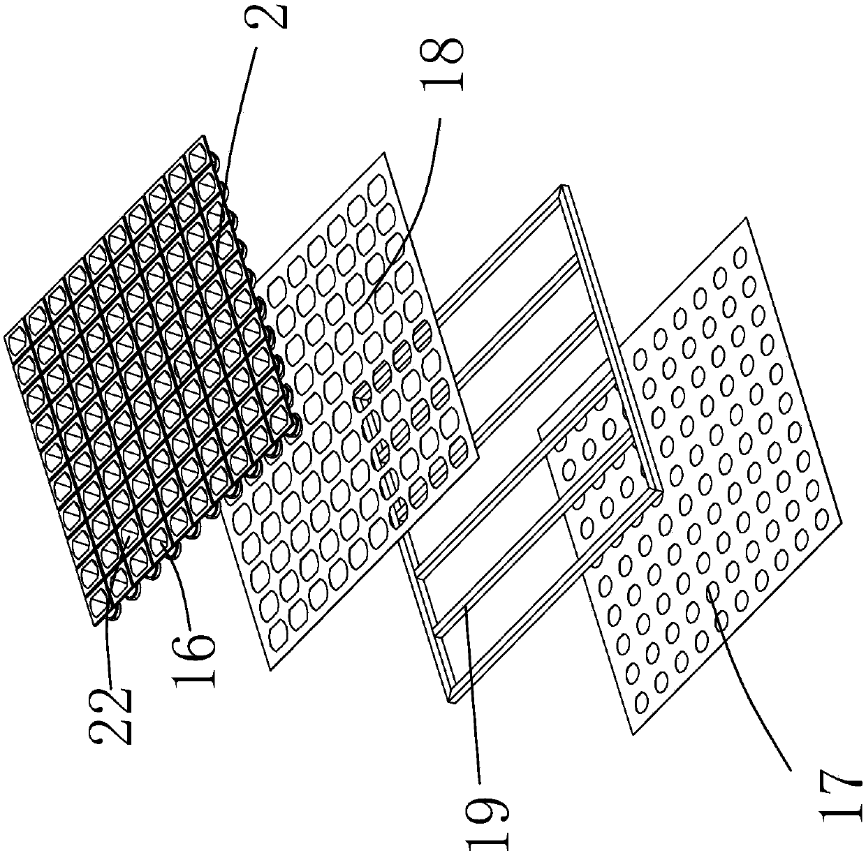
[0020] In the figure, the outer frame part 1; the chassis part 2; the upper fixed part 3; the bottom square tube 4; the column 5; the bottom beam 6; the upper beam 7; Rod 11; three types of stop rod 12; upper high temperature resistant rubber sleeve 13; high temperature resistant block 14; upper fixing hole 15; lower fixing hole 16; first iron sheet 17; second iron sheet 18; supporting chassis 19; casters 20; luggage Frame 21; Lower high temperature resistant plastic sleeve 22.

[0021] Such as figure 1 and Figure 5 As shown, the automotive roof luggage rack universal tooling includes an outer frame portion 1, a chassis portion 2 and an upper fixing portion 3, the chassis portion 2 is arranged at the bottom of the outer...


PUM


Abstract

The invention belongs to the technical field of vehicle parts and provides a universal appliance tooling for a vehicle top luggage rack. The universal appliance tooling comprises an outer frame part,a chassis part and an upper fixed part, wherein the chassis part is arranged at the lower part of the outer frame part, the upper fixed part is arranged at the upper part of the outer frame part, theupper fixed part comprises a plurality of stop levers arranged at intervals, a fixed area is formed between two adjacent stop levers, the fixed area is provided with a plurality of upper fixed holes,the chassis part is provided with a plurality of lower fixed holes, and a single luggage rack to be transported is fixed between the upper fixed holes and the lower fixed holes. Compared with the prior art, the universal appliance tooling provided by the invention has the advantages that factory appliance varieties are reduced so as to be convenient for logistics management; parts can complete transport turnover of all processes of a front stage in an appliance tooling, protection on the appearance surface of the luggage rack can be met, and the luggage rack can not be molten under the high temperature condition; no other substitutes are found yet; and the universal appliance tooling can be shared by 90% or more luggage racks.

Description

technical field [0001] The invention belongs to the technical field of auto parts, and in particular relates to a universal appliance tooling for an auto roof luggage rack. Background technique [0002] At present, there are many luggage rack tools and tools in the auto parts factory. The specifications are not uniform. Each project development must design a special tool and tool, which cannot be used in common with other projects. At present, the tools and tools are not enough or the tools and tools are purchased many times during the development of many projects. After the completion of the project development, the background car will be scrapped, resulting in a lot of waste of resources. The old-fashioned appliance trolley cannot meet the requirements of the luggage rack aging process, and the trolley cannot meet the high temperature of 2800-3500 without melting. Adverse effects, etc., the luggage rack is an exterior decoration that has high requirements on the appearance...

Claims


Application Information

Patent Timeline
IPC IPC(8): B62B3/10
CPCB62B3/102
Inventor 左昌闫贺庆
Owner MINTH AUTOMOTIVE TECH RES & DEV CO LTD
Learn More