CCD detection device with material guiding function

A detection device and material technology, applied in the direction of transportation and packaging, optical testing for flaws/defects, conveyors, etc., can solve problems such as messy placement, speed up detection, and inability to detect in time, so as to improve detection efficiency and reduce entry detection the effect of time

Inactive Publication Date: 2018-02-09
钟立朋
View PDF0 Cites 4 Cited by
  • Summary
  • Abstract
  • Description
  • Claims
  • Application Information

AI Technical Summary

Problems solved by technology

In the CCD detection device, after the materials are loaded, they are placed in a mess, and the detection work cannot be carried out in time. Therefore, how to speed up the detection work in the CCD detection device is a problem considered by technicians.

Method used


Image

  • CCD detection device with material guiding function

Examples


Embodiment

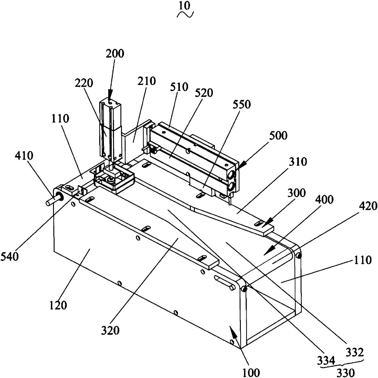
[0022] see figure 1 , the present invention provides a CCD detection device 10 with a material guiding function, comprising: a bracket 100 and a CCD detection unit 200 disposed on the bracket 100 , a guide positioning unit 300 , a horizontal transfer unit 400 and a guide moving unit 500 . It should be noted that the bracket 100 is used to fix the entire CCD detection device; the CCD detection part 200 is used for the CCD detection of the material; the guide positioning part 300 is used for the guide positioning of the material; For conveying materials; the guide moving part 500 is used to move the guide positioning part 300 .

[0023] The bracket 100 includes a first fixing plate 110 , a second fixing plate 120 and a fixing beam 130 fixed between the first fixing plate and the second fixing plate 120 . It should be noted that the fixed beam 130 is fixed to the first fixed plate 110 and the second fixed plate 120 by screws at both ends.

[0024] The CCD detection unit 200 inc...


PUM


Abstract

The invention discloses a CCD detection device with a material guiding function, comprising: a bracket and a CCD detection part arranged on the bracket, a guiding positioning part, a horizontal transmission part and a guiding moving part; the bracket includes a first fixing plate, a second Two fixed plates and a fixed beam fixed between the first fixed plate and the second fixed plate; the CCD detection part includes a detection bracket and a CCD video detector located on the detection bracket; the present invention is a A CCD detection device with a material guiding function, by being provided with a first guide plate and a second guide plate, the material can quickly and accurately enter the CCD detection station, and be detected by a CCD video detector, and, in the CCD detection device Equipped with a horizontal driver and a vertical driver, the two guide plates can be moved and positioned. By moving the two guide plates, the material can be further accelerated into the inspection station, which improves the inspection efficiency and reduces the time for entering the inspection, which is conducive to industrialization and automation. production.

Description

technical field [0001] The invention relates to the field of detection device structure, in particular to a CCD detection device with a material guiding function. Background technique [0002] With the continuous development of society and the continuous progress of science and technology, mechanized and automated production has gradually become a development trend. In the past, the vigorous development of China's manufacturing industry relied on a large number of cheap labor. However, time has changed. With the reduction of new labor population in recent years and the improvement of people's living standards, labor is no longer a cheap resource. It has become more and more common to find a job. In order to meet the needs of production, automated production is gradually valued by the enterprise. In the CCD detection device, after the materials are loaded, they are placed in a mess, and the detection work cannot be carried out in time. Therefore, how to speed up the detecti...

Claims


Application Information

Patent Timeline
Patent Type & Authority Applications(China)
IPC IPC(8): B65G23/04B65G21/20G01N21/89
CPCB65G23/04B65G21/2063G01N21/89
Inventor 钟立朋
Owner 钟立朋
Why Eureka
Try Eureka