Testing apparatus and method for testing torsional rigidity of radial section of piston ring

A technology of torsional rigidity and radial cross-section, applied in the field of piston rings, can solve the problems of complex calculation of piston rings, difficulty in accurate measurement of piston ring torque, and disregard of torsional motion of piston rings, etc., to achieve high test efficiency, improve the fixing effect, The effect of simple structure

Active Publication Date: 2018-02-09
HARBIN ENG UNIV
View PDF5 Cites 6 Cited by
  • Summary
  • Abstract
  • Description
  • Claims
  • Application Information

AI Technical Summary

Problems solved by technology

[0004] Due to the complex calculation of the torsional motion of the piston ring, most scholars do not consider the torsional motion of the piston ring when studying the mechanical properties of the piston ring.
In addition, the application of piston ring torque and twist angle are also difficult to achieve accurate measurement

Method used


Image

  • Testing apparatus and method for testing torsional rigidity of radial section of piston ring
  • Testing apparatus and method for testing torsional rigidity of radial section of piston ring
  • Testing apparatus and method for testing torsional rigidity of radial section of piston ring

Examples


Embodiment Construction

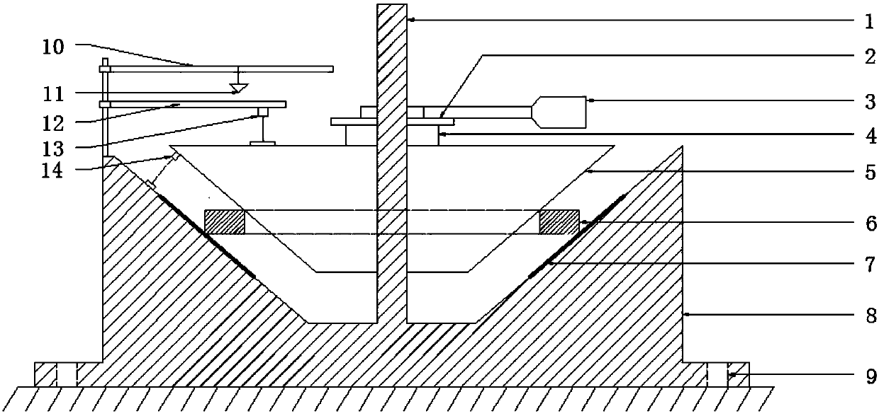
[0037] Combine below Figure 1 ~ Figure 2 This device will be specifically described. The utility model relates to a test device for torsional rigidity of a radial section of a piston ring.

[0038] The purpose of the present invention is achieved in this way, including: piston ring 6, base 8, pressure body 5, force sensor 4, loading handle 3, leveling pendulum 10, plumb 11, displacement measurement pendulum 12, first displacement Sensor 13 and second displacement sensor 14;

[0039] There is a groove on the base 8, and the inner wall of the groove of the base is a circumferentially symmetrical slope. There is a central column 1 in the center of the groove of the base, and the central column 1 is fixedly connected with the base 8; the central column 2 is sequentially arranged from top to bottom. A loading handle 3, a force sensor 4 and a pressure body 5 are installed; the side of the pressure body 5 is a circumferentially symmetrical slope; the piston ring 6 is installed bet...


PUM


Abstract

The invention specifically provides a testing apparatus for testing the torsional rigidity of the radial section of a piston ring, belonging to the field of power machinery. The testing apparatus comprises the piston ring, a base, a pressing body, a force sensor, a loading handle, a leveling swing rod, a plumb, a displacement measuring swing rod, a first displacement sensor and a second displacement sensor, wherein a groove is arranged on the base, and a central column is arranged at the center of the groove on the base; the loading handle, the force sensor and the pressing body are sequentially arranged on the central column from top to bottom; the piston ring is arranged between the side surface of the pressing body and the inner wall of the groove on the base; the circumferential section of the piston ring is perpendicular to the central column; the top of the base is provided with a connecting rod which is provided with the leveling swing rod and the displacement measuring swing rod; the first displacement sensor is installed between the displacement measurement swing rod and the upper surface of the pressing body; and the second displacement sensor is installed between the side surface of the pressing body and the inner wall of the groove on the base. According to the invention, the radial section deformation of the piston ring is taken into consideration, so the precisionof torque determination of the piston ring is high, and accurate torsional rigidity of the radial section of the piston ring can be obtained.

Description

technical field [0001] The present invention relates to a piston ring in the power field, in particular to a test device for the torsional stiffness of the radial section of the piston ring, and also to a test method for the torsional stiffness of the radial section of the piston ring. Background technique [0002] The movement of the piston ring in the ring groove is very complicated, including axial reciprocation, circumferential rotation, and twisting around the circumferential section. Due to the difference in gas pressure between the adjacent ring grooves and lands of the piston ring, the cross section of the piston ring will be twisted and deformed, and then twisted stress will be generated. The torsional movement of the piston around the radial section will cause fatigue and damage to the piston ring, and also affect the air tightness of the piston ring, so the calculation and analysis of the torsional movement of the piston ring is very important. The torsional stif...

Claims


Application Information

Patent Timeline
Patent Type & Authority Applications(China)
IPC IPC(8): G01N3/22
CPCG01N3/22
Inventor 卢熙群罗江龙董庆兵赵滨李彤阳王乃昆张亮吕修颐何山焦博文
Owner HARBIN ENG UNIV
Why Eureka
Try Eureka