Magnetic levitation brake motor

a brake motor and magnetic technology, applied in the direction of dynamo-electric brakes/clutches, dynamo-electric machines, electrical apparatus, etc., can solve the problems of limited torque value, low current, and large consumption of power, so as to reduce torque error and increase overall torque accuracy

Inactive Publication Date: 2016-09-15
HSU HSIU LIN
View PDF3 Cites 0 Cited by
  • Summary
  • Abstract
  • Description
  • Claims
  • Application Information

AI Technical Summary

Benefits of technology

[0008]The primary objective of the present invention is to provide a sort of magnetic levitation brake motor, so as to reduce the torque error generated by automatic screwdriver during operation and the torque accuracy attenuation in long-term operation, so as to increase the overall torque accuracy.
[0009]Another objective of the present invention is to provide a magnetic levitation brake motor, so as to reduce the starting current of automatic screwdriver, and it has slow start and provides braking effect on stop.
[0010]In order to attain Said objectives, the present invention designs a magnetic levitation brake motor, comprising a motor which provides power source; and a magnetic levitation clutch, combined with the shaft of motor, it has alternating magnetic repulsion and attraction, providing the motor with slow start and braking effect. Under the alternating effect of homopolar repulsion and heteropolar attraction when the magnetic levitation clutch is in operation, the motor starting current can be reduced, and the motor has relatively low inertia moment and friction force, reducing the heating and damage of MOSFET controlling drive motor current.

Problems solved by technology

For example, when the automatic screwdriver is being started, a high current supply is usually required, so as to start high-speed operation of motor smoothly, and it must be started for driving screws each time, so it consumes much power.
This starting current is low, but the torque value is limited, and the drive range is limited.
The automatic screwdriver of high torque needs current for starting, consuming power.
The maximum torque value is sometimes reached when implementing driving, the trip of clutch generates considerable counterforce, resulting in torque error in the operator's driving operation, and it is likely to cause occupational injury to the operator in the long run.

Method used


Image

  • Magnetic levitation brake motor
  • Magnetic levitation brake motor
  • Magnetic levitation brake motor

Examples


Embodiment Construction

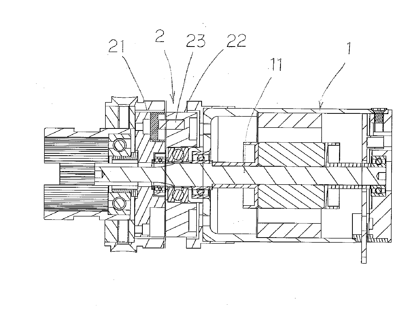
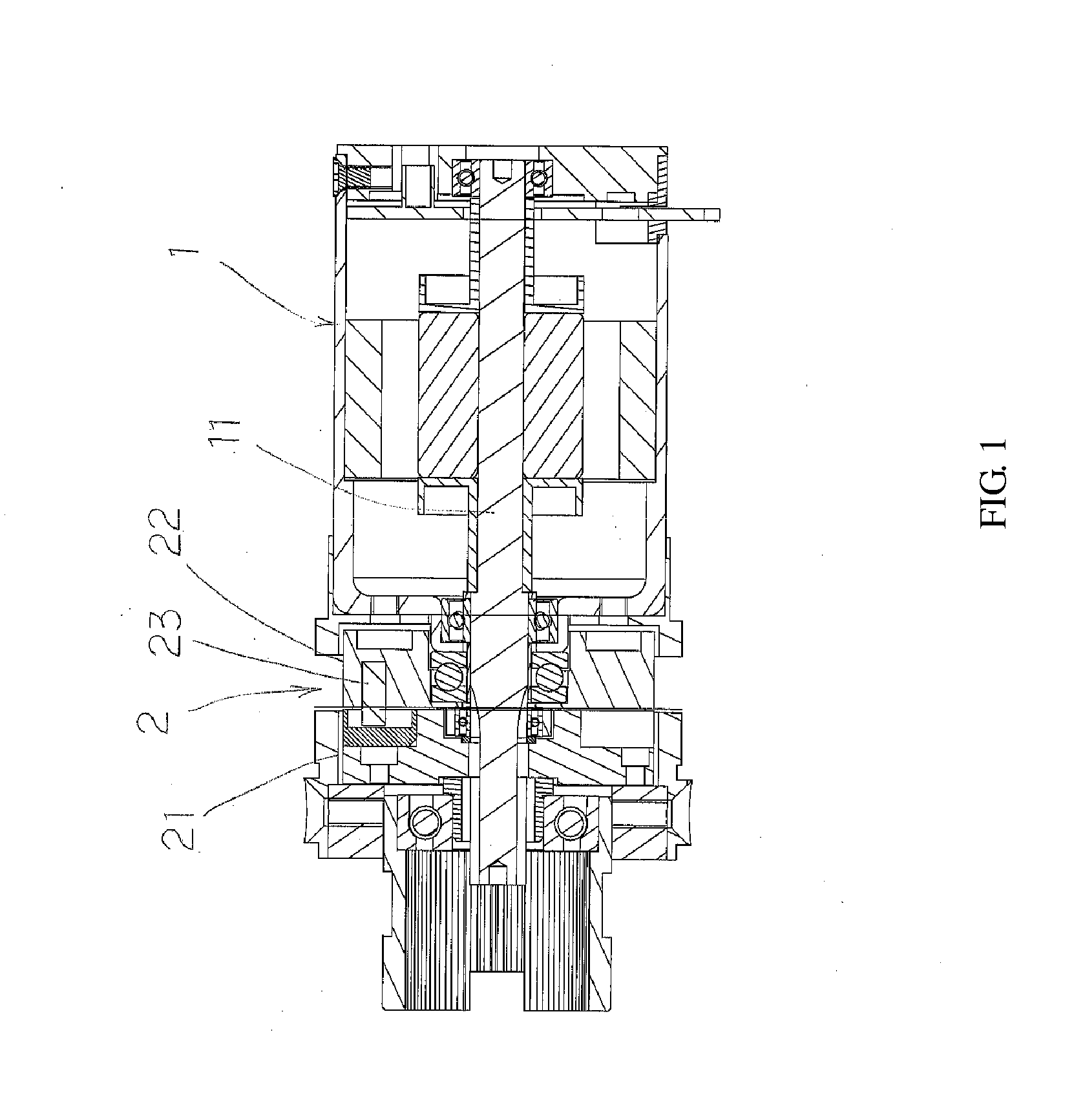
[0028]Referring to FIG. 1 which discloses a magnetic levitation brake motor, comprising a motor (1), providing power source; and a magnetic levitation clutch (2), providing braking effect.

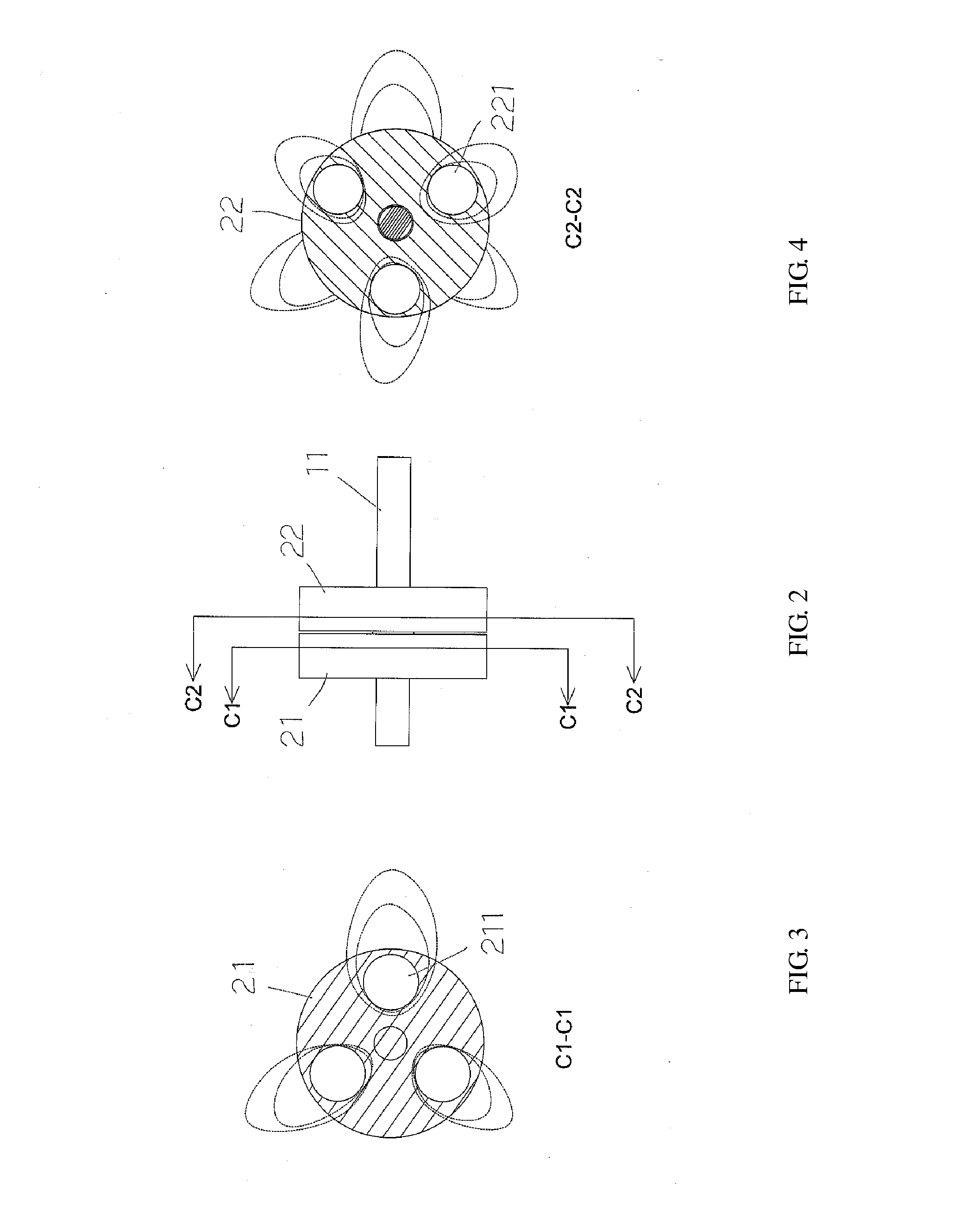
[0029]As shown in FIG. 1-FIG. 5, the shaft (11) of the motor (1) penetrates through the magnetic levitation clutch (2), and they are fixed, so that the motor (1) can drive the magnetic levitation clutch (2) synchronously when it is started; the magnetic levitation clutch (2) comprises of a driving part (21); a passive part (22) contacting the driving part (21); and a latch (23) for connecting the driving part (21) and passive part (22).

[0030]There are at least two magnetic bodies (211) in uniform distribution on the contact surface of the driving part (21) and the passive part (22), in the same way, there are at least two magnetic bodies (221) in uniform distribution on the contact surface of the passive part (22) and driving part (21), and the magnetic body (211) on the surface of the driving part...


PUM


Abstract

A magnetic levitation brake motor, which is very applicable to automatic screwdrivers. A motor providing power output is combined with a magnetic levitation clutch, the alternating effect of homopolar repulsion and heteropolar attraction in the operation of the magnetic levitation clutch can reduce the motor starting current, and the motor has less inertia moment and friction force, reducing the heating and damage of MOSFET controlling drive motor current. In the operation, the magnetic levitation clutch runs when the motor is started, and the inertia moment is increased and the kinetic energy is accumulated. Under a load, the rotation speed of the magnetic levitation clutch decreases and kinetic energy is released to increase the torque. The motor stops when the preset torque is reached. The magnetic levitation clutch keeps running due to inertia moment, but it stops gradually due to the reluctance generated by pole effect.

Description

BACKGROUND OF INVENTION[0001]1. Field of the Invention[0002]The present invention is related to the combinational structure of motor and clutch for automatic screwdrivers, more particularly to a magnetic levitation brake motor which is applicable to automatic screwdrivers.[0003]2. Description of Related Art[0004]When the motor changes from stationary state into operating state, a large kinetic energy shall be provided instantly to destroy the balance, so that the rotor rotates. The lower the rotor load is, the less is the starting kinetic energy required. On the contrary, the higher the rotor load is, the more is the starting kinetic energy required.[0005]For example, when the automatic screwdriver is being started, a high current supply is usually required, so as to start high-speed operation of motor smoothly, and it must be started for driving screws each time, so it consumes much power. In the operation using a fixed torque value to drive general screws, the screw has no load (s...

Claims


Application Information

Patent Timeline
Patent Type & Authority Applications(United States)
IPC IPC(8): H02K7/108
CPCH02K7/108H02K49/065H02K49/10H02K7/11
Inventor HSU, HSIU-LIN
Owner HSU HSIU LIN
Why Eureka
Try Eureka