Optimal sensor layout method for system parameter identification

A system parameter and arrangement method technology, which is applied in the field of system parameter identification to avoid arranging sensors with overlapping information and reduce test costs

Active Publication Date: 2018-02-09
HUNAN UNIV
View PDF3 Cites 10 Cited by
  • Summary
  • Abstract
  • Description
  • Claims
  • Application Information

AI Technical Summary

Problems solved by technology

Solve the problem of parameter identification in all solid structures by placing the position and the minimum number of sensors

Method used


Image

  • Optimal sensor layout method for system parameter identification
  • Optimal sensor layout method for system parameter identification
  • Optimal sensor layout method for system parameter identification

Examples


Embodiment Construction

[0029] Preferred embodiments of the present invention will be specifically described below in conjunction with the accompanying drawings, wherein the accompanying drawings constitute a part of the application and are used together with the embodiments of the present invention to explain the principles of the present invention.

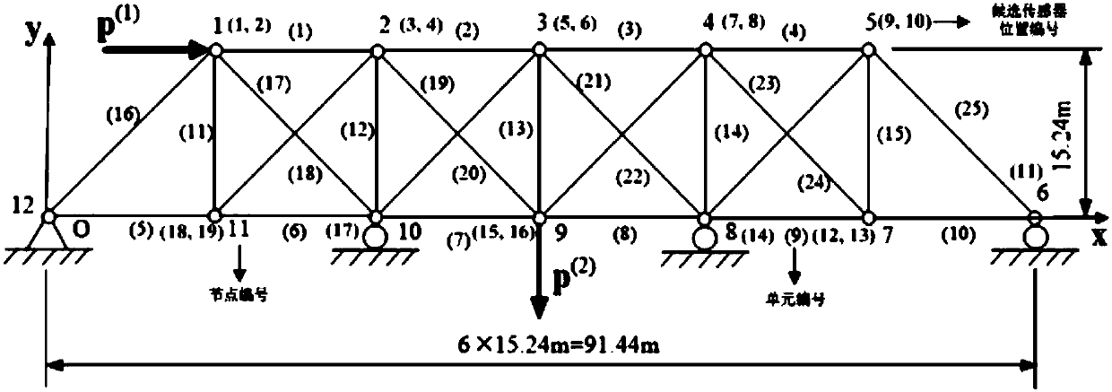
[0030] The method of the present invention can be used for parameter identification of all solid structures, so the sensor arrangement on any mechanical structure can be realized by this method, but in order to illustrate the technical solution of the present invention in more detail, the present invention takes 25 bar truss structures as Examples will be described. Specifically, an optimal sensor arrangement method for system parameter identification includes the following steps:

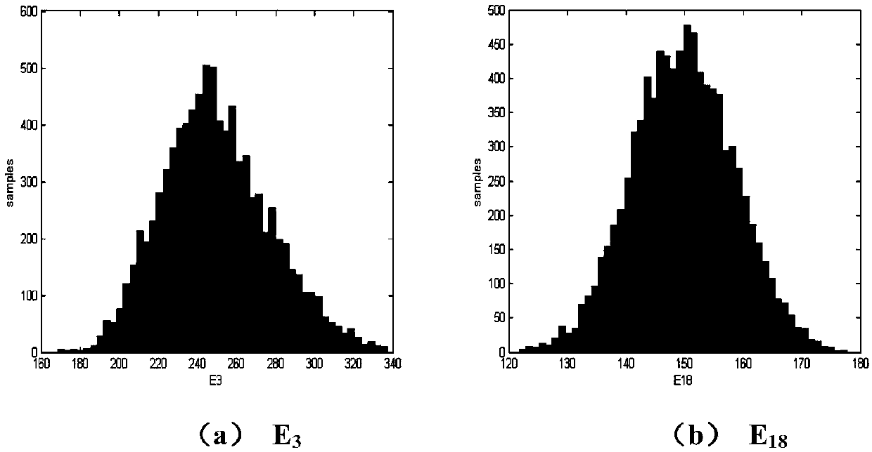
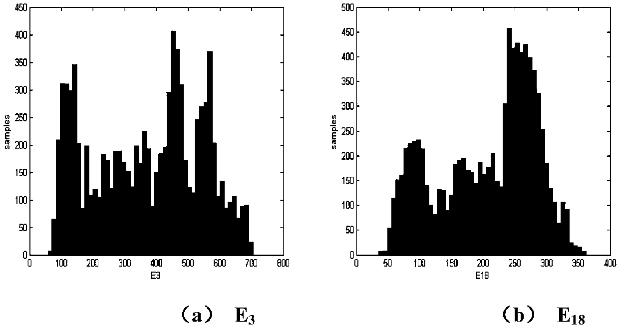
[0031] Step 1: Assuming that the parameters to be identified have a probability distribution form, sampling is performed based on the Monte Carlo method to obtain a sample ...


PUM


Abstract

The invention discloses an optimal sensor layout method for system parameter identification. The method comprises the following steps: firstly supposing that to-be-identified parameters are in a probability distribution form (such as obey normal distribution), sampling the to-be-identified parameters based on the Monte Carlo method, computing the response vector at each candidate sensor, and performing decentration operation on the response vector, namely, subtracting the mean vector by the response vector; secondly, counting the response variance at each candidate sensor, taking the locationwith the maximum response variance as the optimal sensor layout location; thirdly, performing orthogonalization operation on the response vector at the residual candidate sensor and the response vector at the selected sensor to remove the related information, acquiring an independent component of the response vector at the residual candidate sensor, and selecting the location with the maximum independent variance as the suboptimal sensor layout location; and finally, repeating the above-mentioned selection process until the mode of the independent component of the response vector at the residual candidate sensor tends to zero. Through the method disclosed by the invention, the location and number of the optimal sensor required for identifying the system parameter can be determined, and theresponse information of the residual sensor can be completely expressed by the response information at the selected sensor.

Description

technical field [0001] The invention relates to the technical field of system parameter identification, in particular to an optimal sensor arrangement method for system parameter identification. Background technique [0002] System status assessment, model correction, etc. all need to obtain effective information through sensors. Reasonable arrangement of sensors has become one of the key technologies for structural health monitoring and system parameter identification. For large and complex systems or structures, there are usually many different sensor locations. Although the more sensors are used, the description of structural characteristics will be more accurate. However, considering the limitations of technology, site and economic conditions, it is not realistic to arrange sensors in all locations. , too many sensors will also introduce a lot of redundant information, so usually only a small number of sensors are arranged in limited positions. At the same time, a reaso...

Claims


Application Information

Patent Timeline
Patent Type & Authority Applications(China)
IPC IPC(8): G06F17/50
CPCG06F30/20G06F30/23
Inventor 刘杰欧阳衡姜潮韩旭
Owner HUNAN UNIV
Why Eureka
Try Eureka