
Display device drive system and method

A display device and drive system technology, applied to static indicators, instruments, etc., can solve the problems of storage space and circuit board design space waste, and achieve the effects of improving utilization rate, reducing resource waste, and reducing quantity

Active Publication Date: 2018-02-09
TCL CHINA STAR OPTOELECTRONICS TECH CO LTD
View PDF8 Cites 25 Cited by
  • Summary
  • Abstract
  • Description
  • Claims
  • Application Information

AI Technical Summary

Problems solved by technology

At this time, if figure 1 As shown, in the prior art, a first flash memory chip 200 and a second flash memory chip 300 are respectively configured for each timing controller 100, and each of the first flash memory chip 200 and the second flash memory chip 300 stores a large amount of free space, resulting in Minimize the waste of memory space and circuit board design space

Method used


Image

  • Display device drive system and method
  • Display device drive system and method
  • Display device drive system and method

Examples


Embodiment Construction

[0035] In order to further illustrate the technical means adopted by the present invention and its effects, the following describes in detail in conjunction with preferred embodiments of the present invention and accompanying drawings.

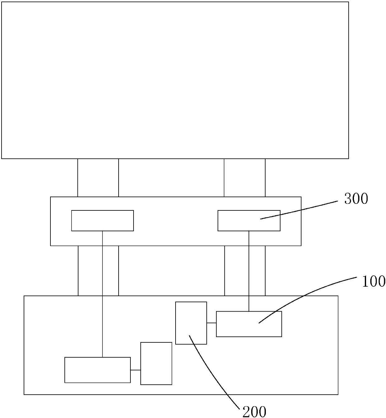
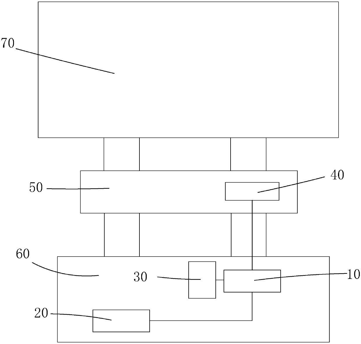
[0036] see figure 2 , the present invention provides a display device driving system, comprising: a master timing controller 10, at least one slave timing controller 20 connected to the master timing controller 10, and a first flash memory chip 30 connected to the master timing controller 10 ;

[0037] The first flash memory chip 30 is used to store the configuration code of the master timing controller 10 and the configuration code of the slave timing controller 20;

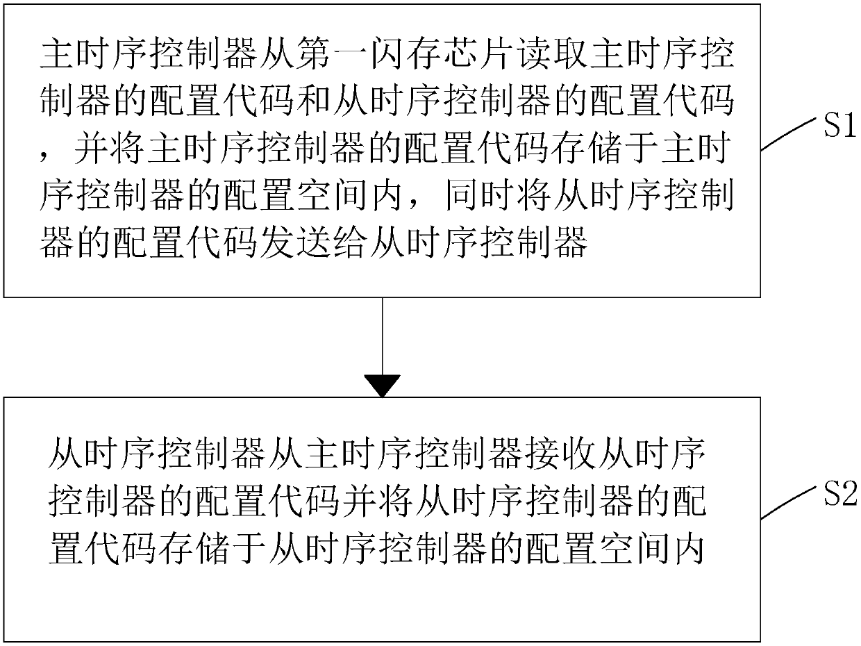
[0038] The master timing controller 10 is used to read the configuration code of the master timing controller 10 and the configuration code of the slave timing controller 20 from the first flash memory chip 30, and store the configuration code of the master timing controller 10 ...


PUM


Abstract

The invention provides a display device drive system and method. The system comprises a main time sequence controller, at least one slave time sequence controller connected with the main time sequencecontroller, and a first flash memory chip connected with the main time sequence controller. The first flash memory chip is used for storing a configuration code of the main time sequence controller and configuration codes of the slave time sequence controllers. During operation, the main time sequence controller reads the configuration code of the main time sequence controller and configuration codes of the slave time sequence controllers from the first flash memory chip, and transmits the configuration codes of the slave time sequence controllers to the slave time sequence controllers. The slave time sequence controllers receive the configuration codes of the slave time sequence controllers from the main time sequence controller, thereby completing the configuration of the time sequencecontrollers. The system can reduce the number of flash memory chips, improves the utilization rate of the storage space and a circuit board design space, and reduces the waste of resources.

Description

technical field [0001] The present invention relates to the field of display technology, in particular to a display device driving system and method. Background technique [0002] With the development of display technology, liquid crystal displays (Liquid Crystal Display, LCD) and other flat display devices are widely used in mobile phones, televisions, personal Various consumer electronic products such as digital assistants, digital cameras, notebook computers, and desktop computers have become the mainstream of display devices. [0003] A flat panel display device generally includes a display panel (Panel) and an external driving circuit, and the external driving circuit generally includes: a timing control chip (TCON), a power management chip (Power manage IC) and programmable gamma correction chip (P-gamma IC), etc., wherein the timing control chip is mainly used to convert low-voltage differential signaling (Low-Voltage Differential Signaling, LVDS) signals into low-am...

Claims


Application Information

Patent Timeline
IPC IPC(8): G09G3/36
CPCG09G3/3611
Inventor 肖光星
Owner TCL CHINA STAR OPTOELECTRONICS TECH CO LTD
Features
  • Generate Ideas
  • Intellectual Property
  • Life Sciences
  • Materials
  • Tech Scout
  • Unparalleled Data Quality
  • Higher Quality Content
  • 60% Fewer Hallucinations
Learn More