
A self-elevating tower crane with variable angle

A self-elevating, tower crane technology, applied in the direction of cranes, etc., can solve the problems of difficult attachment and installation, small attachment angle, difficult position selection of tower cranes, etc., and achieves low manufacturing and installation difficulty, large attachment angle, and good economic benefits. Effect

Active Publication Date: 2019-06-11
CHINA CONSTR THIRD ENG BUREAU GRP CO LTD
View PDF7 Cites 0 Cited by
  • Summary
  • Abstract
  • Description
  • Claims
  • Application Information

AI Technical Summary

Problems solved by technology

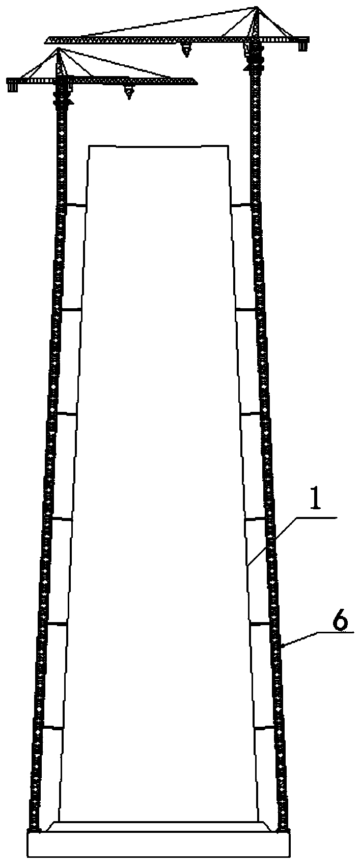
[0004] Aiming at the problems existing in the prior art, such as difficulty in selecting the position of the tower crane when the structure is tilted, too long attachment distance between the tower crane body and the structure, difficulty in attachment installation, small attachment angle, and low safety, the present invention provides a variable angle The self-elevating tower crane, which sets the transformation section on the tower body, through the change of the angle of the transformation section itself, the tower body of the tower crane can be tilted, while the free height is still vertical, thereby changing the inclination angle and shape of the tower body, In order to adapt to the angle of the attached installation side of structures such as buildings, bridge towers, or cooling towers, the length of each attachment is basically the same. The invention has a wide range of applications, can reduce the difficulty of construction on site, and improve the intelligence of building construction.

Method used


Image

  • A self-elevating tower crane with variable angle
  • A self-elevating tower crane with variable angle
  • A self-elevating tower crane with variable angle

Examples


Embodiment Construction

[0026] In order to make the object, technical solution and advantages of the present invention clearer, the present invention will be further described in detail below in conjunction with the accompanying drawings and embodiments. It should be understood that the specific embodiments described here are only used to explain the present invention, not to limit the present invention.

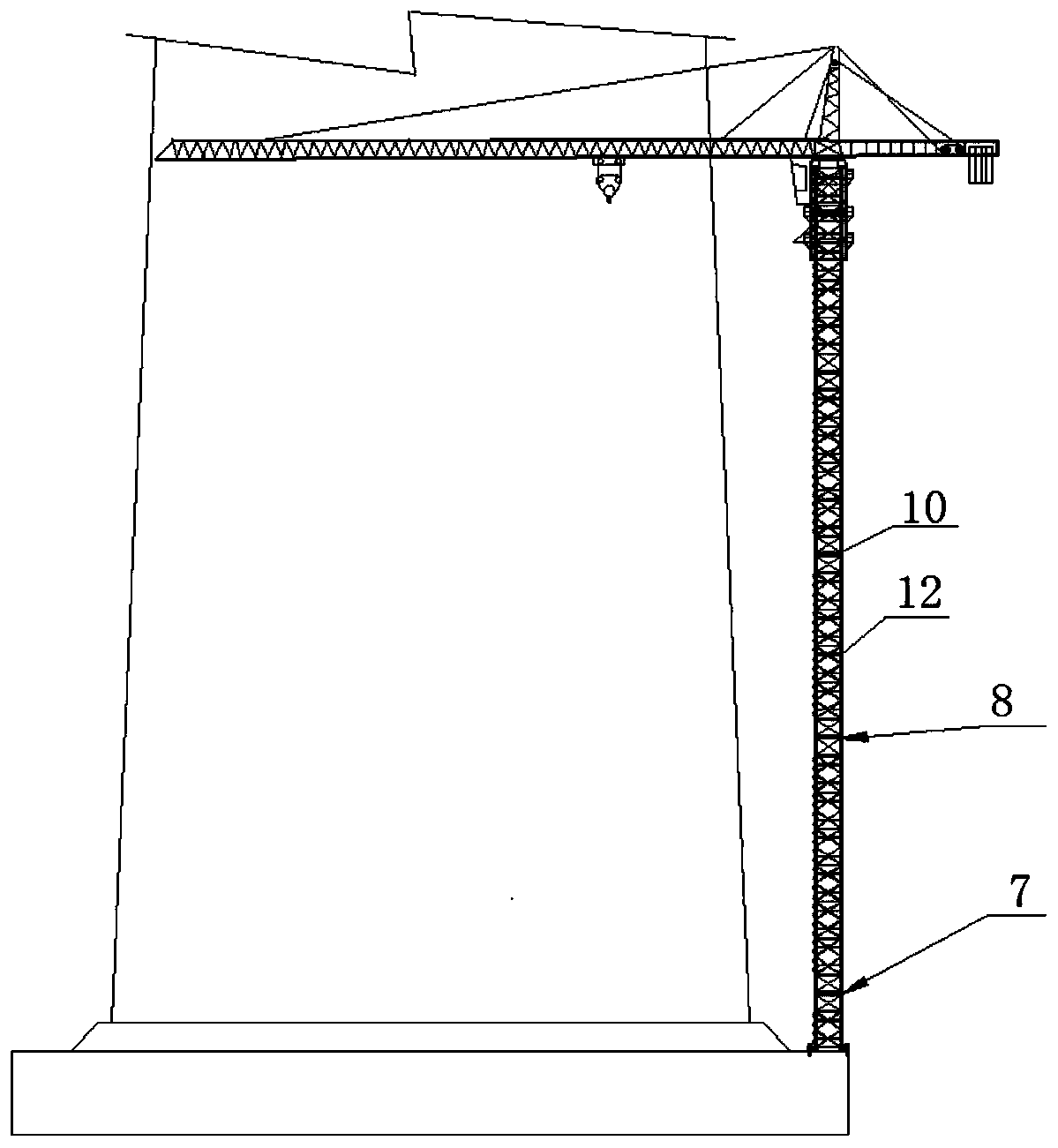
[0027] In a preferred embodiment of the present invention, as Figure 2-Figure 8 As shown, a self-elevating tower crane with a variable angle, the tower crane includes a tower body 6, the tower body includes a standard section 12 and a transformation section (7, 8, 10), the standard sections are connected sequentially from top to bottom, and the interval between the transformation sections is A certain distance is arranged between two adjacent standard joints, and the conversion joint includes an upper connecting piece 13, a lower connecting piece 14 and a hinge 15, the upper connecting piece 13 is...


PUM


Abstract

The invention discloses a variable angle self-elevating tower crane. The tower crane comprises a tower body; the tower body comprises standard joints and converting joints; the standard joints are sequentially connected from top to bottom; each converting joint is arranged between every two adjacent standard joints at a certain interval, and comprises an upper connection piece, a lower connectionpiece and a hinging piece; each upper connection piece is connected with the corresponding standard joint located above the upper connection piece; each lower connection piece is connected with the corresponding standard joint located below the lower connection piece; and each hinging piece is installed between the corresponding upper connection piece and the corresponding lower connection piece,and is used for making the upper connection piece and the lower connection piece relatively rotate to adjust an included angle between the upper connection piece and the lower connection piece, so that the inclination angle of the corresponding standard joint located between every two adjacent converting joints can be consistent with the inclination angle of the side face of a structure. By meansof the variable angle self-elevating tower crane, the inclination angle and the shape of the tower body can be changed, so that the variable angle self-elevating tower crane can adapt to the angle ofthe attached installing side face of a building, a bridge tower column or a cooling tower or other structures, and the lengths of attached pieces are made basically consistent.

Description

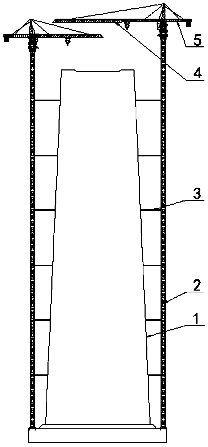
technical field [0001] The invention belongs to the technical field of building construction, and in particular relates to a variable-angle self-elevating tower crane. Background technique [0002] Jack-up tower crane is the most commonly used lifting equipment on construction sites. It is an indispensable equipment on the construction site of structures such as buildings, bridge towers or cooling towers. As the construction height of towers and other structures increases, self-elevating tower cranes continue to increase in height. After the tower crane exceeds the specified free height, it needs to be installed and attached, and the next attachment should be installed at intervals of a certain height according to the specified value. [0003] Such as figure 1 As shown, the existing tower crane includes the existing tower body 2, the existing attachments 3, the tower crane boom 4 and the tower crane balance arm 5. , then as the height changes, the distance between the exis...

Claims


Application Information

Patent Timeline
Patent Type & Authority Patents(China)
IPC IPC(8): B66C23/28B66C23/62
CPCB66C23/286B66C23/62
Inventor 张琨王辉周勇王开强刘晓升陈波曹振杰叶贞朱磊磊
Owner CHINA CONSTR THIRD ENG BUREAU GRP CO LTD
Learn More