Supercharge Your Innovation With Domain-Expert AI Agents!

Method and system for an exhaust catalyst

A catalyst and exhaust temperature technology, which is applied in the electronic control of exhaust treatment devices, exhaust devices, exhaust treatment, etc., can solve problems such as reduced capacity and impact on emission quality.

Active Publication Date: 2018-02-13
FORD GLOBAL TECH LLC
View PDF7 Cites 1 Cited by
  • Summary
  • Abstract
  • Description
  • Claims
  • Application Information

AI Technical Summary

Problems solved by technology

Oxygen saturation may cause the catalyst to convert NO adsorbed on the catalyst x The reduction of the capacity, thereby affecting the emission quality

Method used


Image

  • Method and system for an exhaust catalyst
  • Method and system for an exhaust catalyst
  • Method and system for an exhaust catalyst

Examples


Embodiment Construction

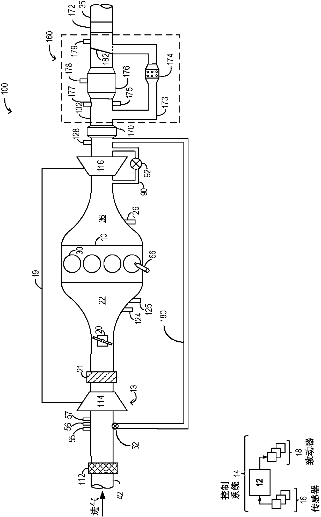
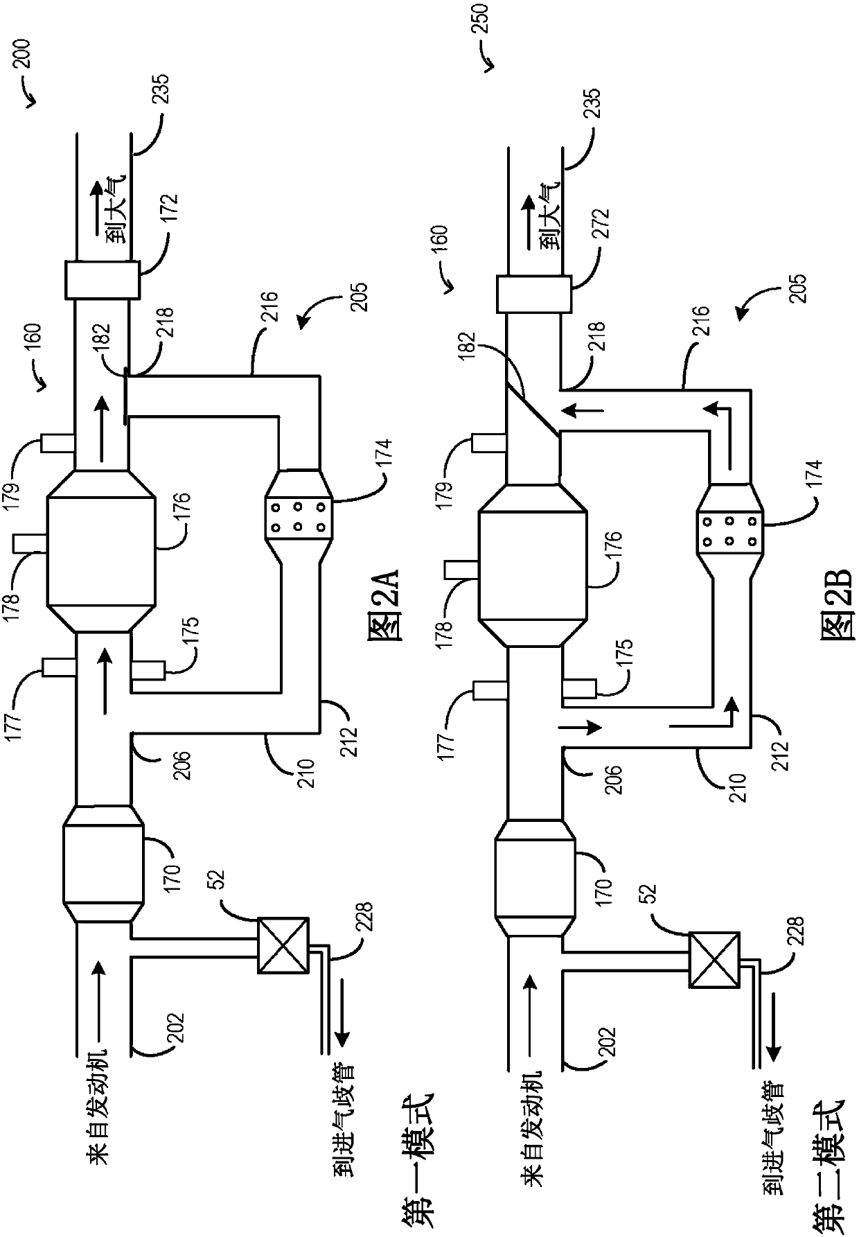
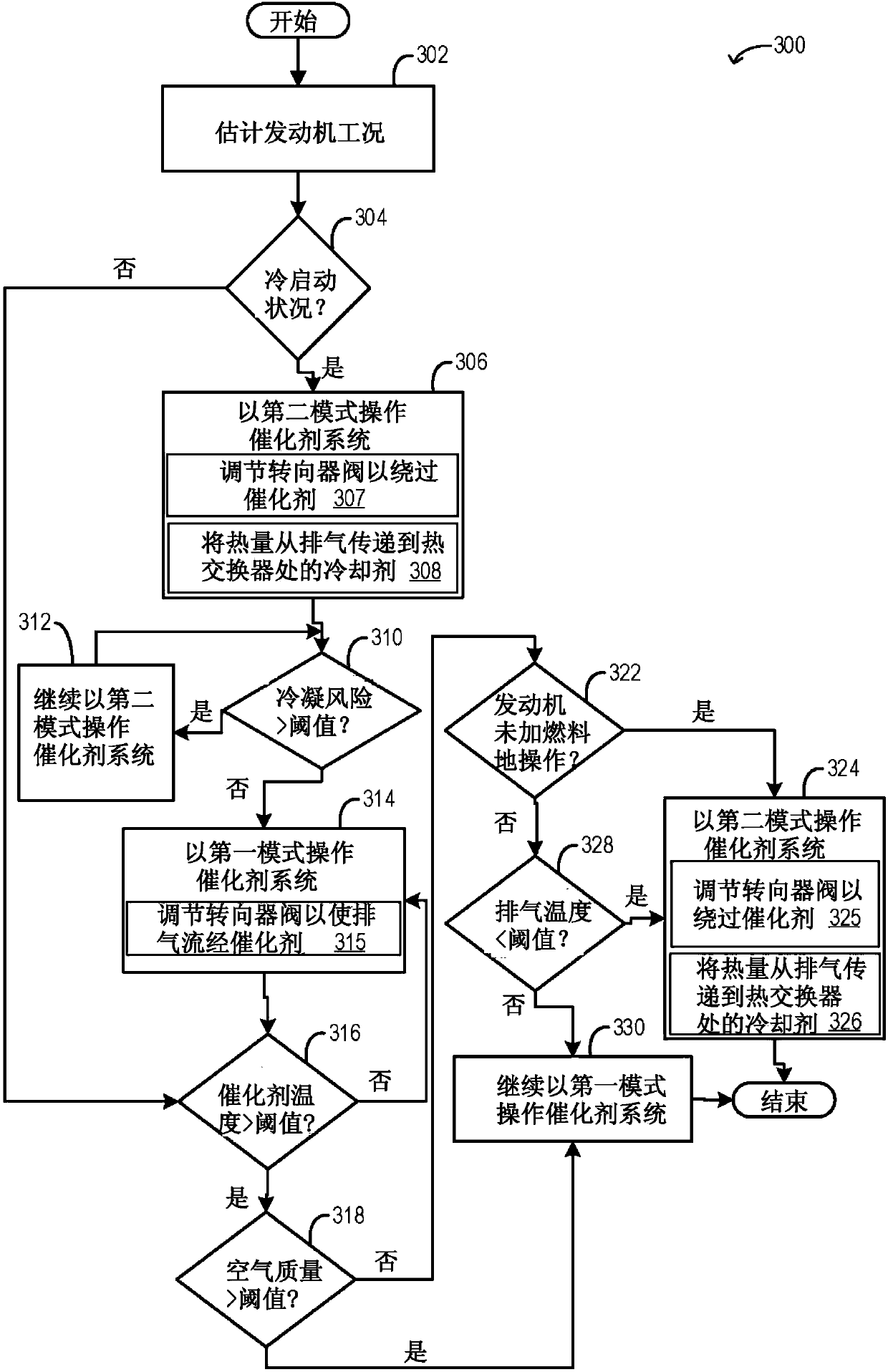
[0014] The following description relates to systems and methods for increasing the efficiency of exhaust catalyst systems and reducing engine emissions. exist figure 1 An example engine system including an exhaust catalyst system with a bypass passage housing a heat exchanger is shown in . refer to Figure 2A and Figure 2B A detailed description figure 1 different operating modes of the exhaust catalyst system. The engine controller can be configured to execute control routines such as image 3 Example routine to change the position of the diverter valve coupled to the main exhaust passage to regulate flow through figure 1 Exhaust from the exhaust catalyst system in the system. exist Figure 4 The different operating modes of the exhaust catalyst system are listed in . refer to Figure 5 show figure 1 Example Operation of an Exhaust Catalyst System.

[0015] figure 1 Aspects of an example engine system 100 including engine 10 are shown schematically. In the illus...


PUM


Abstract

The invention relates to a method and a system for an exhaust catalyst. Methods and systems are provided for operating an engine exhaust aftertreatment system to increase the efficiency of an exhaustunderbody catalyst and reduce engine emissions. In one example, a bypass passage may be coupled to a main exhaust passage and during conditions which may adversely affect functionality of the underbody catalyst, exhaust may be opportunistically routed via the bypass passage avoiding the underbody catalyst. Exhaust heat may be recovered via a heat exchanger coupled to the bypass passage, and the heat may be used for engine heating, and passenger cabin heating.

Description

technical field [0001] The present description generally relates to methods and systems for controlling a vehicle engine to increase the efficiency of an exhaust aftertreatment system and reduce engine emissions. Background technique [0002] An emission control device, such as an underbody catalyst, coupled to the exhaust passage of an internal combustion engine, reduces combustion byproducts such as nitrogen oxides, carbon monoxide, and hydrocarbons. Engine cold-start emissions generated prior to light-off of the underbody catalyst can contribute a significant proportion to total exhaust emissions. The efficiency of the underbody catalyst may be affected by exhaust temperature and may be suboptimal outside of a certain temperature range. Furthermore, catalyst functionality may be adversely affected by oxygen loading in the catalyst above a threshold. [0003] Accordingly, various methods have been developed to selectively route exhaust gas through exhaust catalysts based...

Claims


Application Information

Patent Timeline
IPC IPC(8): F01N3/20F01N9/00F01N5/02F01N13/00
CPCF01N13/0093F01N3/2053F01N5/02F01N9/00F01N2560/14F01N2900/1602F01N2900/1404F01N2900/1402F01N2900/12F01N2900/08F01N3/10F01N2240/22F01N2240/36F01N2260/08F01N2410/03F01N2410/06F01N2560/06F01N2560/07F01N2900/1411F01N2900/1628F01N3/005Y02T10/12Y02T10/40F01N2260/02F01N2390/00
Inventor M·J·尤瑞奇J·N·尤瑞
Owner FORD GLOBAL TECH LLC
Features
  • R&D
  • Intellectual Property
  • Life Sciences
  • Materials
  • Tech Scout
  • Unparalleled Data Quality
  • Higher Quality Content
  • 60% Fewer Hallucinations
Learn More