Eureka AIR delivers breakthrough ideas for toughest innovation challenges, trusted by R&D personnel around the world.

Vertical multi-tube bundle type forced-cooling vortex tube cold-heat separation device

A technology of forced cooling and separation of cold and heat, applied in refrigerators, refrigeration components, refrigeration and liquefaction, etc., can solve problems such as difficult collection and recycling of heat, space saving of vertical structure, difficulty of horizontal balance, etc., and reach the structural size range Wide, simple and feasible structure, easy to guarantee the accuracy of manufacturing and processing

Pending Publication Date: 2018-02-13
DALIAN UNIV OF TECH
View PDF7 Cites 1 Cited by
  • Summary
  • Abstract
  • Description
  • Claims
  • Application Information

AI Technical Summary

Problems solved by technology

However, this kind of horizontal structure device does have a lot of inconvenience in the process of installation, debugging, disassembly and maintenance, because the weight of each single part in the device is not light, if mechanical tools such as cranes cannot be used, the installation should be maintained to maintain horizontal balance It is very difficult, so it is not easy to install; in addition, the horizontal structure occupies a relatively large area, which is not as space-saving as the vertical structure; in addition, the vortex tube cooling and heating are complementary, explained from the theory of energy conservation. The cooling capacity required as much as possible must generate corresponding heat. The more heat generated inside, the more cooling capacity will be obtained. Another important point is to do a good job of cooling the fluid at the hot end. Greatly improve cooling temperature and efficiency
Prior to this, the heat dissipation of the hot end fluid was only natural cooling by air cooling, the cooling effect was not good, and the cooling efficiency was extremely low. However, if the forced cooling method and means of circulating water cooling are used, the efficiency and effect can be significantly improved and enhanced.
In addition, the heat in other refrigeration devices in the past is difficult to collect and recycle

Method used


Image

  • Vertical multi-tube bundle type forced-cooling vortex tube cold-heat separation device
  • Vertical multi-tube bundle type forced-cooling vortex tube cold-heat separation device
  • Vertical multi-tube bundle type forced-cooling vortex tube cold-heat separation device

Examples


Embodiment Construction

[0027] Below in conjunction with accompanying drawing and specific embodiment the present invention will be further described:

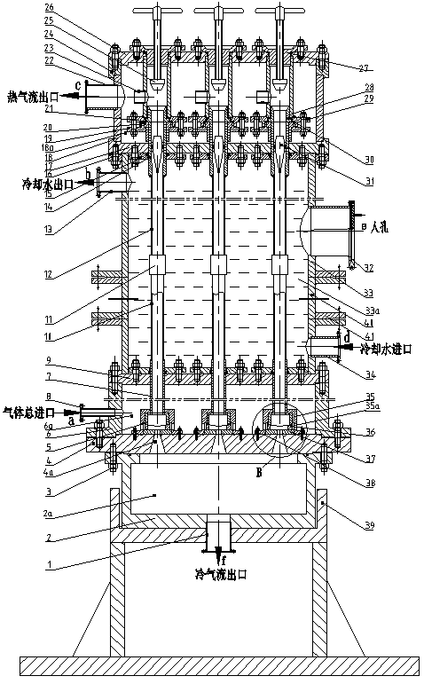
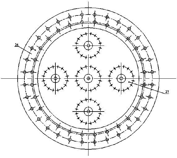
[0028] figure 1 , 2 , 3, 4, and 5 show a structural diagram of a vertical multi-tube bundle forced cooling vortex tube cold and heat separation device. In the figure, the device as a whole has a vertical multi-tube bundled structure, and consists of four chambers from top to bottom: the hot end collection chamber 18a, the water cylinder jacket chamber 33a, the air intake chamber 6a and the cold air collection chamber 2a , the hot end collection chamber 18a is formed by the fixed connection of the hot chamber shell 18 and the lower end cover 17 of the hot chamber, the upper flange 24 of the hot chamber and the upper end cover 26 of the hot chamber; , a replaceable barrel nipple 40, a connecting flange 41, an air intake chamber cover 9, an upper flange 16 of the water tank jacket and a lower end cover 17 of the thermal chamber are fixedly connected; ...


PUM


Abstract

The invention provides a vertical multi-tube bundle type forced-cooling vortex tube cold-heat separation device and belongs to the technical field of pressure gas refrigeration and high-low temperature separation. The vertical multi-tube bundle type forced-cooling vortex tube cold-heat separation device comprises a plurality of vertex tubes and is provided with integrated air inlet cavity, a coldair collection cavity, and a hot end collection cavity, wherein the integrated air inlet cavity, the cold air collection cavity and the hot end collection cavity are independently sealed, and thus thewhole process of continuous air intake and cold-heat separation can be completed simultaneously. A forced cooling method based on circulating water is adopted by the vertical structure, and thus theefficiency can be remarkably improved. As the overall space capacity is improved through a bundle device, the contradiction between the basic application condition of vertex tubes in a large device and the large-flow treatment requirement is avoided. The refrigeration capacity and the heating capacity can be greatly improved in multiples. The vertical multi-tube bundle type forced-cooling vortex tube cold-heat separation device is suitable for large industrial production occasions, integrates refrigeration and heating and can separate cold energy from heat energy. The vertical multi-tube bundle type forced-cooling vortex tube cold-heat separation device is suitable for refrigerating and heating different types of gas and has the advantages of being combined, integrated, skid mounted, detachable and the like.

Description

technical field [0001] The invention relates to a vertical multi-tube bundle type forced cooling vortex tube cold and heat separation device, which belongs to the technical field of pressure gas throttling and pressure reduction, gas phase medium refrigeration and high and low temperature separation applications. Background technique [0002] The vortex tube technology is a technology that directly uses the pressure energy of the gas to finally separate the gas into cold and hot airflows. When working, the pressurized gas enters the annular gas storage buffer chamber outside the vortex chamber along the inlet channel, and under the action of the pressure difference between the inlet and outlet, it passes through a single or multiple nozzles and is injected into the vortex chamber at a high speed tangentially along the pipe wall. Strong swirling motion is generated in the vortex chamber, thereby inducing the vortex effect. After the vortex transformation, it is separated into...

Claims


Application Information

Patent Timeline
IPC IPC(8): F25B9/04F25B43/00
CPCF25B9/04F25B43/00
Inventor 朱彻胡大鹏刘培启代玉强邹久朋于洋张大为张健
Owner DALIAN UNIV OF TECH
Why Eureka
Eureka Blog
Learn More