Display device

A display device and display panel technology, applied in the direction of instruments, optics, lenses, etc., can solve the problems of restricting the application of floating display and the inability to realize multi-layer display of floating images, and achieve the effect of three-dimensional dynamic visual effect

Pending Publication Date: 2018-02-13
SHANGHAI TIANMA MICRO ELECTRONICS CO LTD
View PDF12 Cites 18 Cited by
  • Summary
  • Abstract
  • Description
  • Claims
  • Application Information

AI Technical Summary

Problems solved by technology

However, in the prior art, for a floating display device with a certain structure, the height of the displayed floating image is constant, and it is impossible to realize the multi-layer display of the floating image, which actually limits the application of the floating display to a certain extent.

Method used


Image

  • Display device
  • Display device
  • Display device

Examples


Embodiment Construction

[0028] In order to further explain the technical means and effects of the present invention to achieve the intended purpose of the invention, the specific implementation, structure, Features and their functions are described in detail below.

[0029] An embodiment of the present invention provides a display device, and the display device includes:

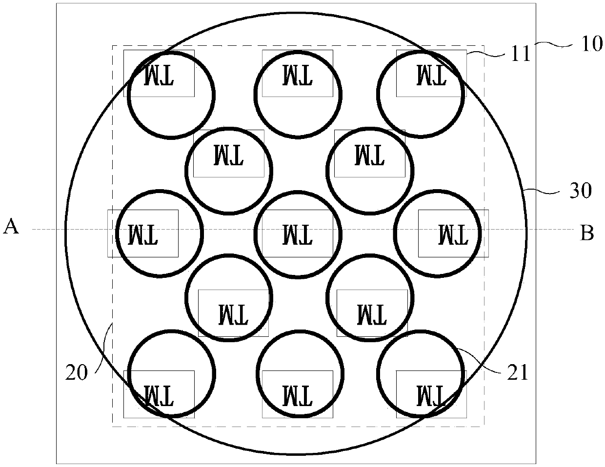
[0030] A display panel, including a plurality of display units;

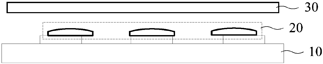
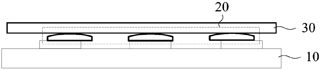
[0031] A microlens group, the microlens group is located above the light-emitting side of the display panel, the microlens group includes a plurality of microlens units, and the microlens units are arranged in one-to-one correspondence with the display unit, the microlens The distance between the center of the lens unit and the center of the display unit gradually increases from the center position to the edge position of the display panel;

[0032] The liquid lens is arranged on the side of the microlens group away from the display panel, and is used to realize mu...


PUM


Abstract

The invention discloses a display device. The display device comprises a display panel, a micro-lens group and a liquid lens, wherein the micro-lens group is positioned above a light exiting side of the display panel and comprises a plurality of micro-lens units; the micro-lens units are in one-to-one correspondence to the display units; the distance from the center of each micro-lens unit to thecenter of the corresponding display unit is gradually increased from the center of the display panel to the edge of the display panel; the liquid lens is arranged on the side, which is away from the display panel, of the micro-lens group, and is used for changing the phase of incident light to realize multi-layered displaying of suspended images. According to the technical scheme provided by the embodiment, the distance from the suspended images shown by the display device to the display panel is variable, multi-layered suspended display of the display device is realized, and thus, the three-dimensional dynamical visual effect is achieved.

Description

technical field [0001] Embodiments of the present invention relate to a floating display technology, and in particular, to a display device. Background technique [0002] With the development of science and technology and the improvement of people's living standards, people's requirements for display devices are not limited to simply transmitting two-dimensional plane information, but hope that they can provide more real, three-dimensional, and more physical and Three-dimensional image information of psychological depth cues. [0003] The current common 3D display device generally adopts the principle of parallax type 3D display, realizes the separation of the left and right views through a cylindrical lens array or a grating array and makes them enter the left and right eyes of the observer respectively, and uses binocular parallax to make people produce stereoscopic perception. However, since it can only reflect parallax information, it is difficult to match convergence a...

Claims


Application Information

Patent Timeline
IPC IPC(8): G02B27/22G02B26/00G02F1/1343G02F1/29G02B30/27
CPCG02B26/005G02F1/134309G02F1/29G02B30/27G02F1/133526G02B30/52G02F1/294G02B3/0006G02F2201/122G02B26/06
Inventor 刘耀阳牛磊徐健李嘉灵
Owner SHANGHAI TIANMA MICRO ELECTRONICS CO LTD
Why Eureka
Try Eureka