Lens member and light-emitting device using same

Active Publication Date: 2014-07-24
CITIZEN ELECTRONICS CO LTD +1
View PDF4 Cites 34 Cited by
  • Summary
  • Abstract
  • Description
  • Claims
  • Application Information

AI Technical Summary

Benefits of technology

[0022]According to the present invention, the following effects are achieved.
[0023]The lens member and the light-emitting device according to the present invention has a diffraction grating structure that is annularly arranged around a periphery of a Fresnel lens to diffract light from a light source and to emit the light as diffracted light from a light-exi

Problems solved by technology

However, in each of the above-described Fresnel lenses, when top ends of the prisms have an acute angle formed from a prism incident surface and a prism reflection surface, metal molds for the prisms that are to be filled with a resin are formed to have narrow top ends, and accordingly, a resin may not fully enter therein.
This causes problems of degradation in performance such as front illuminance of the light-emission surface of the Fresnel lens and the like.
As a result, the lens thickness is disadvantageously increased.
This disadvantageously makes it difficult to maximize utilization efficiency of t

Method used


Image

  • Lens member and light-emitting device using same
  • Lens member and light-emitting device using same
  • Lens member and light-emitting device using same

Examples


Embodiment Construction

[0042]Hereinafter, embodiments of a lens member and a light-emitting device using the lens member according to the present invention will be described with reference to the accompanying drawings. Note that, in some of the drawings for use in the following description, a drawing scale is properly changed so that respective members and forms are sized to be recognizable.

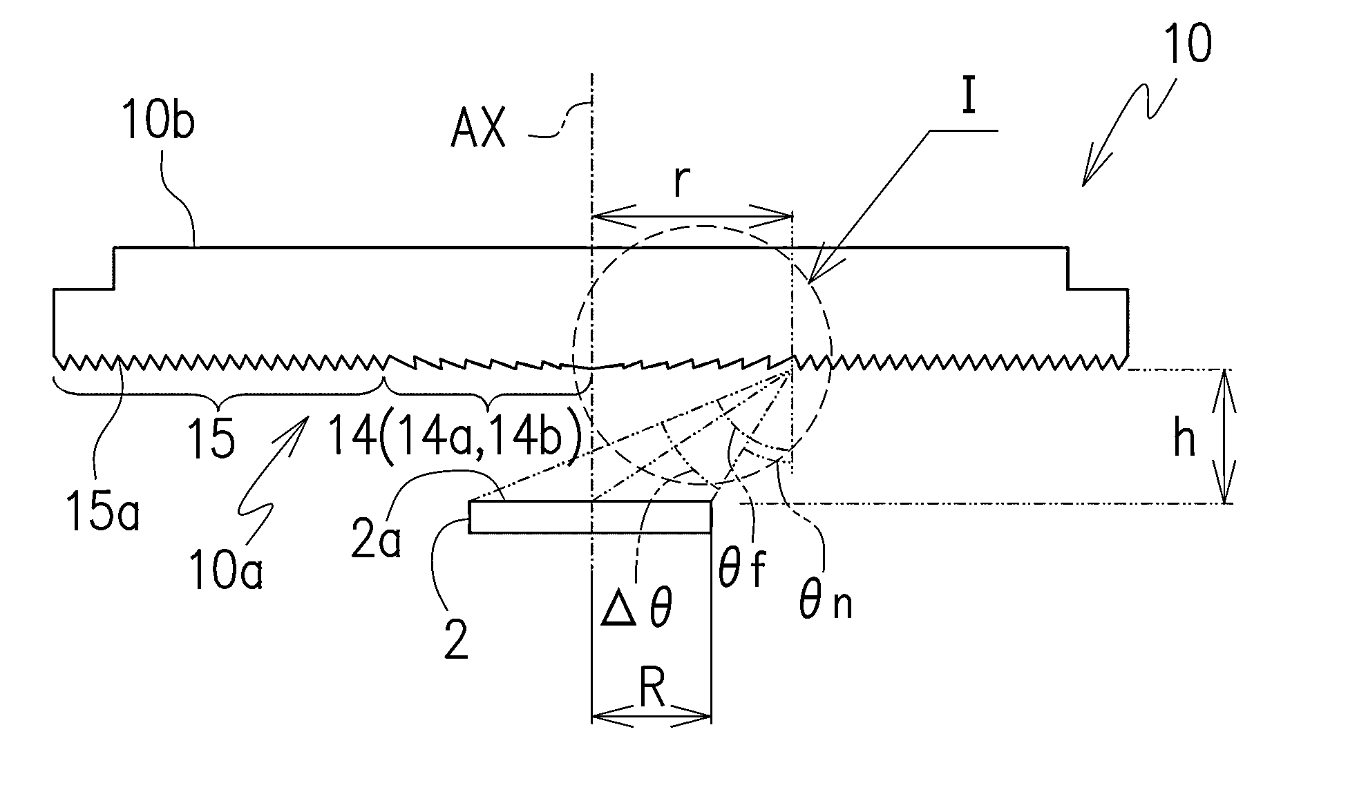
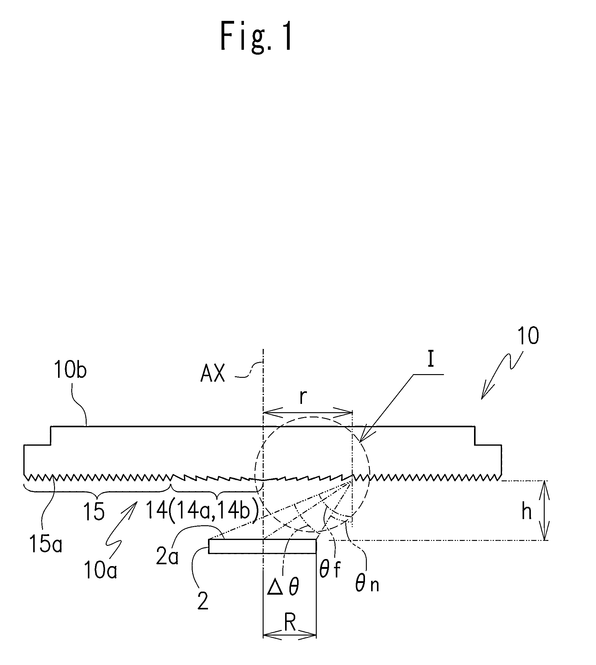
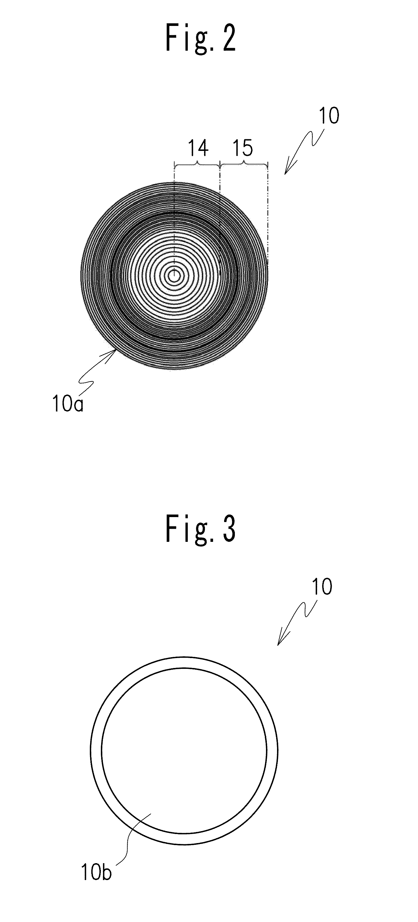
[0043]As illustrated in FIG. 1, a lens member 10 in the present embodiment has a light-incident side 10a, a light reflection surface 10b that is opposite to the light-incident side 10a, a Fresnel lens 14 arranged on a center axis AX that passes through a center of the light-incident side 10a, and a diffraction grating structure 15 arranged around a periphery of the Fresnel lens 14 and arranged to be centered around the center axis AX. In the embodiment illustrated in FIGS. 1 through 4, the lens member 10 is illustrated as a circular-plate-shaped lens. Note that the center axis AX is an imaginary line indicating the cen...


PUM


Abstract

A lens member includes a light-incident side; a light-exit side that is opposite to the light-incident side, a Fresnel lens arranged on a center axis that passes through a center of the light-incident side, and a diffraction grating structure arranged around a periphery of the Fresnel lens and having a center through which the center axis passes. Also, it is disclosed that the Fresnel lens may include a first Fresnel lens and a second Fresnel lens, the first Fresnel lens includes annular prisms that are divided from a convex lens and having a center through which the center axis of the light-incident side passes, and the second Fresnel lens includes annular prisms that are divided from a TIR lens and arranged around the periphery of the first Fresnel lens, centering around the center axis of the light-incident side.

Description

TECHNICAL FIELD[0001]The present invention relates to a lens member and a light-emitting device including the lens member and a light source that is arranged to face the lens member.BACKGROUND ART[0002]In recent years, more and more light-emitting devices, such as illuminations, projectors, flashes, and headlights and tail lamps of automobiles, are using light emitting diodes (LEDs) as a light source. In such light-emitting devices, especially in devices using a narrow directional LED as a light source, a lens that collects or collimates the light emitted from the light-emission surface of the LED is used. A convex refractive lens is generally used as such a lens. Since the convex refractive lens is thick at the convex portion, it has been also proposed to adopt a Fresnel lens in order to make the lens thinner.[0003]A lens for lighting fixtures has conventionally been proposed (see Patent Literature 1). The lens has a grating-shape refracting prism portion provided in a central part...

Claims


Application Information

Patent Timeline
IPC IPC(8): F21V5/04F24S23/30
CPCF21S48/115F21S48/1283F21S48/215F21S48/2212F21S48/236F21V5/002F21V5/04F21V5/045F21V7/0091F21Y2101/02F21K9/10G02B3/08G02B5/1866G02B5/188F24J2/085G02B19/0028G02B19/0061G02B5/1814F21K9/20F21K9/69F21S41/143F21S41/275F21S43/14F21S43/26F21S43/315F21Y2115/10F24S23/31
Inventor MIYASHITA, JUNJIKAYANUMA, YASUAKIMATSUMOTO, KENJI
Owner CITIZEN ELECTRONICS CO LTD
Why Eureka
Try Eureka