Integrated gas control device

Inactive Publication Date: 2005-12-29
KITZ SCT
View PDF4 Cites 34 Cited by
  • Summary
  • Abstract
  • Description
  • Claims
  • Application Information

AI Technical Summary

Benefits of technology

[0037] The invention covered concerns an integrated gas control device that, during the attachment of the individual integration units, enables each integration unit to be easily positioned and simply inserted and further enables the integration unit to be infallibly and simply joined in a connected state to a flow path and consequently imparts high accuracy to the formed flow path.
[0038] The invention concerns an integrated gas control device which, even in the case of having gas flow paths disposed in a multiplicity of series relative to one flow path plate, enables the flow paths to be efficiently disposed inside the flow

Problems solved by technology

For this reason, the flow path plate requires a proper thickness and inevitably occupies a large size.
When the flow path plate is formed of a stainless steel, for example, the large size occupied by the flow path plate is at a disadvantage in adding to the cost of material and adding to t

Method used


Image

  • Integrated gas control device
  • Integrated gas control device
  • Integrated gas control device

Examples


third embodiment

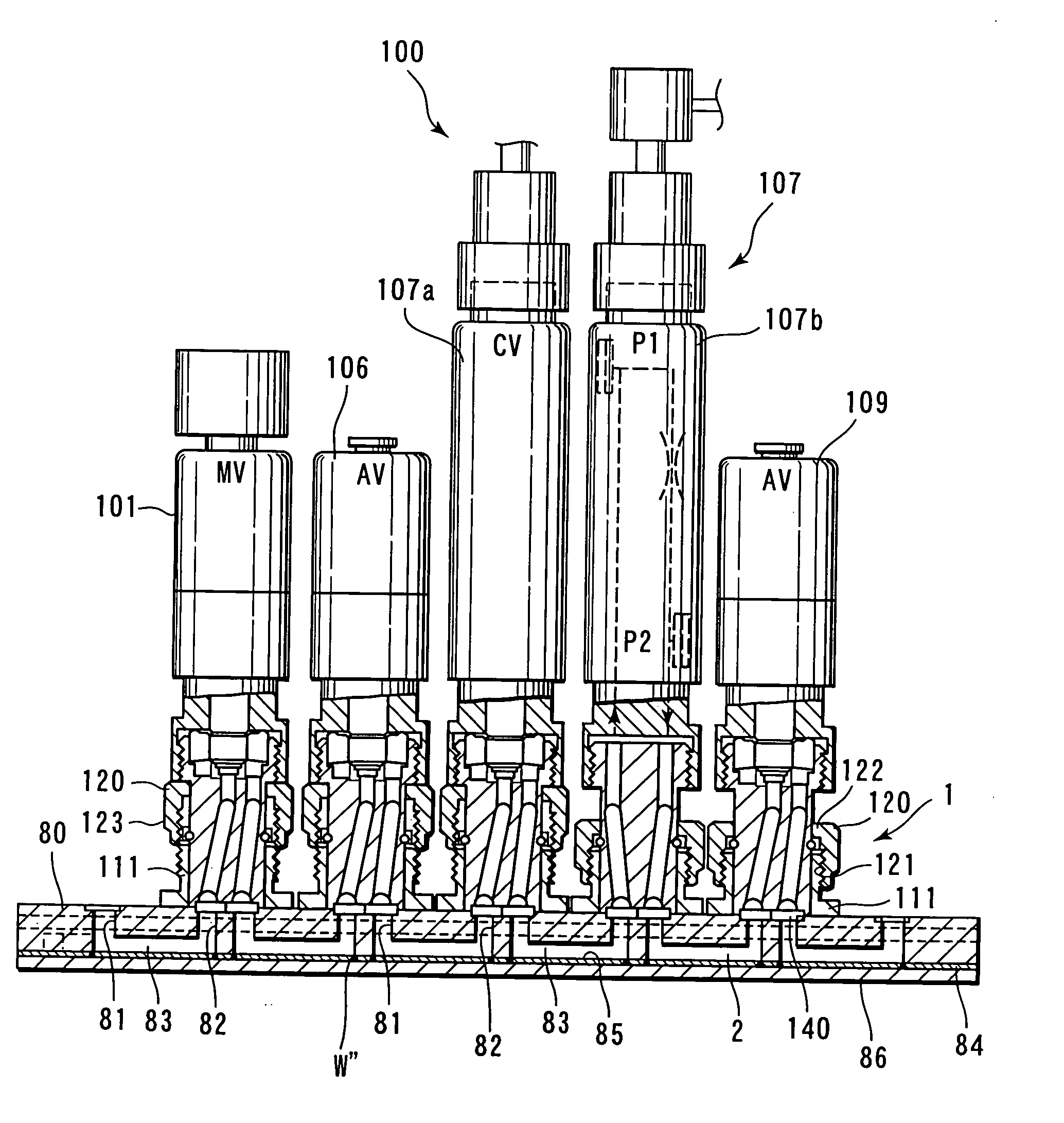
[0079]FIG. 15 illustrates the integrated gas control device contemplated by this invention. A flow path plate 80 is a flow path plate provided in the interior thereof with a gas flow path 83 and a seal plate 84 is a plate for covering at least substantially the whole surface of an opening groove part 85 side formed in the flow path plate 80. By fixing this seal plate 84, a gangway 81 on the entrance side and a gangway 82 on the exit side and the opening groove part 85 are closely sealed and further a reinforcing plate 86 is superposed on the seal plate 84 and consequently enabled to reinforce it. The flow path plate 80 and the seal plate 84 are fixed in a closely sealed state at the welding point W″ by means of welding, such as electronic beam welding, laser welding or spot welding. This welding is carried out in such a manner as to give rise to a circumferential contact portion between the opening groove part 85 and the seal plate 84 and is completed in a short span of time by form...

fourth embodiment

[0080]FIG. 16 and FIG. 17 illustrate the integrated gas control device contemplated by this invention. It is so configured as to seal closely an opening groove part 155 formed in a flow path plate 150 with a seal plate 154 and fix the integration unit 100 with a center lock mounting means using a retaining tubular body 111 and a union nut 120. FIGS. 18 and 19 illustrate an integrated gas control device that has a bypass formed halfway in the length of the gas controlling line. In the case of a configuration having a purging flow path 63 intersect a gas flow path 62 of a flow path plate 61 as illustrated in FIG. 18B, it is enabled to provide a gas controlling line adapted to detour the purging flow path 63 by causing a flow path plate 72 furnished in the interior thereof with a bypass flow path 73 to be fixed with a fixing bolt 66 so as to establish connection between an exit flow path 65 and an entrance flow path 64 of the flow path plate 61. Thus, the gas controlling line is allowe...


PUM


Abstract

An integrated gas control device comprising a flow path plate provided with entrance and exit holes penetrating the flow path plate in a direction of wall thickness thereof to form entrance side gangways and exit side gangways, opening groove parts opened in one or both of opposite face sides of the flow path plate and adapted to connect the entrance side and exist side gangways, seal plates for closely sealing the opening groove parts to form gas flow paths in the flow path plate, and integration units, including automatic valves, each having a flow path that are so mounted on the flow path plate as to connect the flow path to the entrance and exit holes of the flow path plate and so disposed as to allow supply of a gas including a process gas.

Description

BACKGROUND OF THE INVENTION [0001] 1. Field of the Invention [0002] This invention relates to an integrated gas control device for controlling the flow rate of a process gas by means of various sorts of hardware to be integrated, such as manually operated valves, automatic operation valves and mass flow controllers, which device is used in the operation of processing semiconductors, liquid crystals and the like. [0003] 2. Description of Related Art [0004] The flow path plate that has mounted thereon the hardware to be integrated, such as valves mentioned above, has a flow path hole formed in the interior thereof for the purpose of connecting the flow path on the exit side of a unit of hardware to the entrance side of the adjoining unit of hardware. This flow path hole is generally formed by a drilling work with a processing machine. The flow path hole is formed in a V shape or a concave shape, for example. The flow path hole has an inlet connected to the exit side of a unit of hardw...

Claims


Application Information

Patent Timeline
IPC IPC(8): F15B13/00F15B13/08F16K27/00
CPCF15B13/0814F15B13/0835F16K27/003F15B13/0892F15B13/086Y10T137/87885
Inventor IWABUCHI, TOSHIAKI
Owner KITZ SCT
Why Eureka
Try Eureka