Swing shearing device

A technology of shearing device and shearing mechanism, which is applied to shearing devices, accessories of shearing machines, shearing machine equipment, etc., can solve the problems of wasting plates and time-consuming

Inactive Publication Date: 2009-05-27
CHERY AUTOMOBILE CO LTD
View PDF0 Cites 34 Cited by
  • Summary
  • Abstract
  • Description
  • Claims
  • Application Information

AI Technical Summary

Problems solved by technology

When it is necessary to produce special-shaped stamping parts such as parallelogram, isosceles trapezoid, right-angle trapezoid, etc., it is necessary to cut rectangular sheets first, and then cut them into the required shape, which is not only time-consuming, but also wastes sheets. Therefore, it is necessary to design a Brand new swing shear

Method used


Image

  • Swing shearing device
  • Swing shearing device
  • Swing shearing device

Examples


Embodiment Construction

[0027] The present invention will be further described below in conjunction with the accompanying drawings.

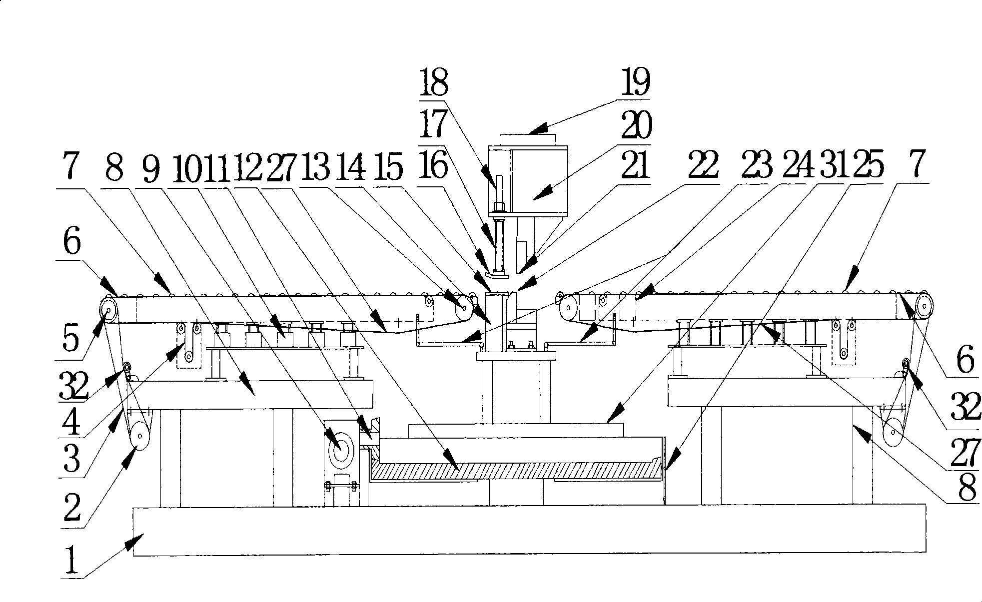
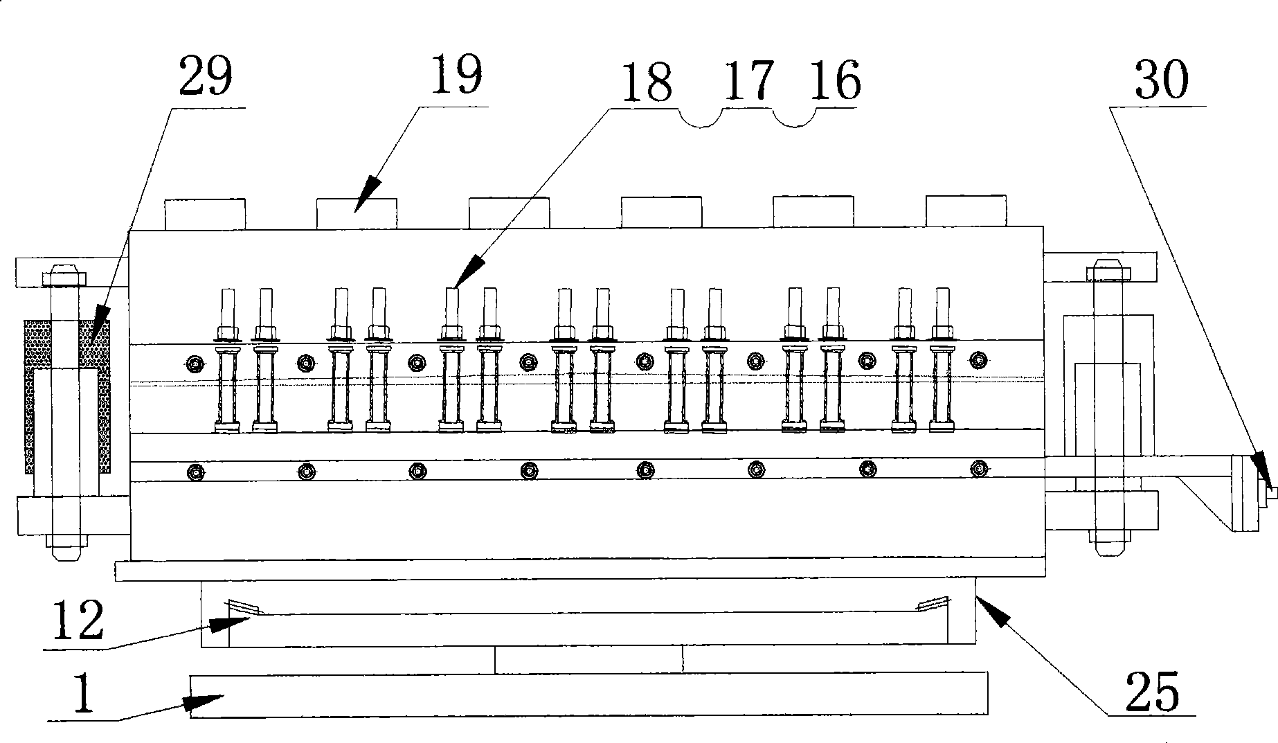
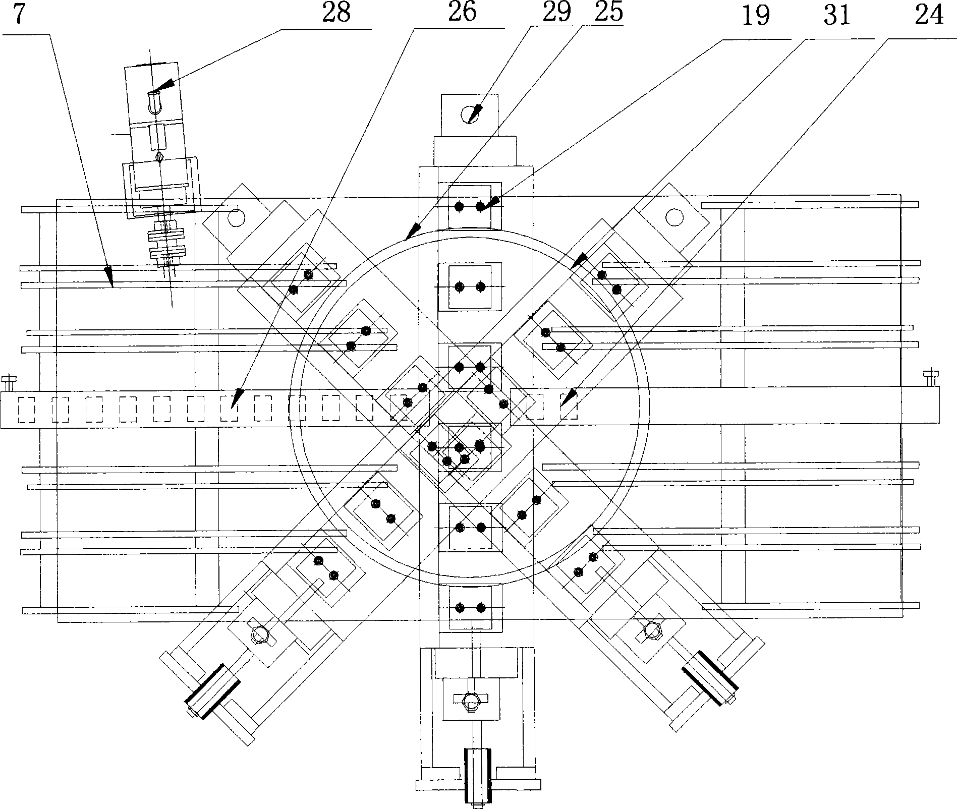
[0028] Such as figure 1 , 2 , As shown in 3, the swing shearing device is composed of four mechanisms, which can be divided into an entry-side transmission mechanism, a gear transmission mechanism, a shearing mechanism, and an exit-side transmission mechanism. The four parts are all installed on the base 1, and four T-shaped slots are opened on the base 1, and the base 1 and the workbench of the press are fixed by T-shaped bolts.

[0029] Such as figure 1 As shown, the gear transmission mechanism is decelerated by the servo motor 28 through the reduction box 9, and drives the driving bevel gear 11 to move. For perimeter protection. The top of the driven disc gear 12 is provided with supports for installing the upper and lower tool mounting brackets 14, 20, and the supports are fixed on the disc support 31 of the shearing mechanism, so that the overall shearing mech...


PUM


Abstract

The invention discloses a swinging cutting device, comprising an installing soleplate, a gear transmission mechanism, a cutting mechanism, an entrance side conveying mechanism and an exit side conveying mechanism; wherein, the gear transmission mechanism consists of a servo motor, a reduction box, a driving bevel gear and a driven disc gear; wherein, the servo motor and the reduction box are fixed on the soleplate; the driven disc gear is horizontally assembled on the soleplate by a bearing and is then connected with a shaft by a spline; the top is fixed with the disc frame of the cutting mechanism; the cutting mechanism is arranged on the disc frame of the cutting mechanism; the servo motor drives the reduction box so as to drive the driving bevel gear to rotate; the driving bevel gear and the driven disc gear are meshed, so as to drive the cutting mechanism by the driven disc gear to freely rotate in a range between +45 degrees and -45 degrees corresponding to the soleplate. The swinging cutting device can not only produce rectangular panels, but also produce allotypic panels, thereby greatly saving cost of steel coil panel and improving productive efficiency.

Description

technical field [0001] The invention relates to an oscillating shearing device for automobile cover steel plate or metal strip. Background technique [0002] In the uncoiling and shearing operation of steel coils in the automotive industry, continuous flying shears are usually used to obtain rectangular sheets of a certain size, that is, transverse shearing operations. When it is necessary to produce special-shaped stamping parts such as parallelogram, isosceles trapezoid, right-angle trapezoid, etc., it is necessary to cut rectangular sheets first, and then cut them into the required shape, which is not only time-consuming, but also wastes sheets. Therefore, it is necessary to design a Brand new swing shear equipment. Contents of the invention [0003] The present invention solves the situation that only rectangular sheets can be produced in the uncoiling and transverse shearing operation, and proposes a swing shear that can produce not only rectangular sheets but also s...

Claims


Application Information

Patent Timeline
Patent Type & Authority Applications(China)
IPC IPC(8): B23D15/08B23D15/12B23D33/00B23D33/02
Inventor 陈厚富程念枫王素粉盛伦旺
Owner CHERY AUTOMOBILE CO LTD
Why Eureka
Try Eureka