Illumination device and projector

a technology of illumination device and projector, which is applied in the direction of lighting and heating apparatus, instruments, optical elements, etc., can solve the problems of difficult application of illumination device to liquid crystal projector, difficult to sufficiently reduce the temperature rise of fluorescent layer, and complicated so as to prevent the deterioration of fluorescent layer, the manufacturing process of rotating fluorescent plate is relatively simple, and the effect of simple manufacturing process

Active Publication Date: 2011-09-22
SEIKO EPSON CORP
View PDF4 Cites 91 Cited by
  • Summary
  • Abstract
  • Description
  • Claims
  • Application Information

AI Technical Summary

Benefits of technology

[0008]An advantage of the invention is to provide an illumination device, which can obtain a plurality of colored light beams using the light source device for emitting the excitation light, can make the manufacturing process of the rotating fluorescent plate relatively simple, and can be applied to a liquid crystal projector. Further, the invention has an advantage of providing a projector equipped with such an illumination device.
[0009]1. According to an aspect of the invention, there is provided an illumination device including a light source device adapted to emit an excitation light beam, and a rotating fluorescent plate having a single fluorescent layer formed on a circular disk, which can be rotated by a motor, continuously along a circumferential direction of the circular disk. The single fluorescent layer converts a part or whole of the excitation light beam into a fluorescent light beam that includes two or more colored light beams.
[0010]Therefore, according to the illumination device of this aspect of the invention, since there are provided the light source device for emitting the excitation light and the rotating fluorescent plate provided with the fluorescent layer for converting a part or the whole of the excitation light into the fluorescent light that includes two or more colored light beams, it becomes possible to obtain the a plurality of colored light beams using t

Problems solved by technology

However, in the illumination device of the related art, since the two types of fluorescent layers need to be formed on the circular disk, there arises a problem that the manufacturing process of the rotating fluorescent plate becomes complicated.
Further, in the illumination device of the related art, since the types of the colored light beams emitted from the illumination device are sequentially switched at high rate in accordance with the rotation of the rotating fluorescent plate, there exists a problem that it is difficult to apply the illuminatio

Method used


Image

  • Illumination device and projector
  • Illumination device and projector
  • Illumination device and projector

Examples


first embodiment

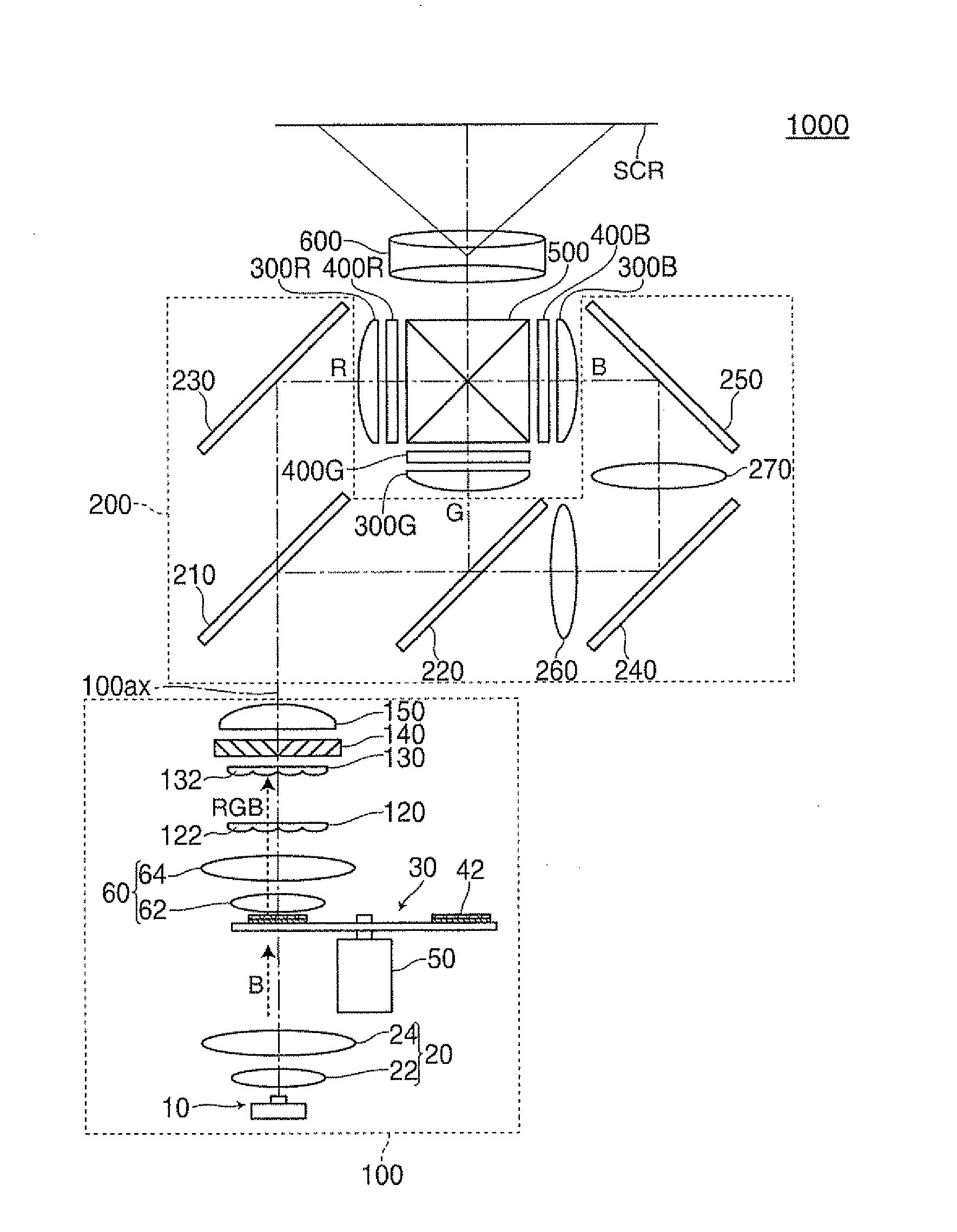
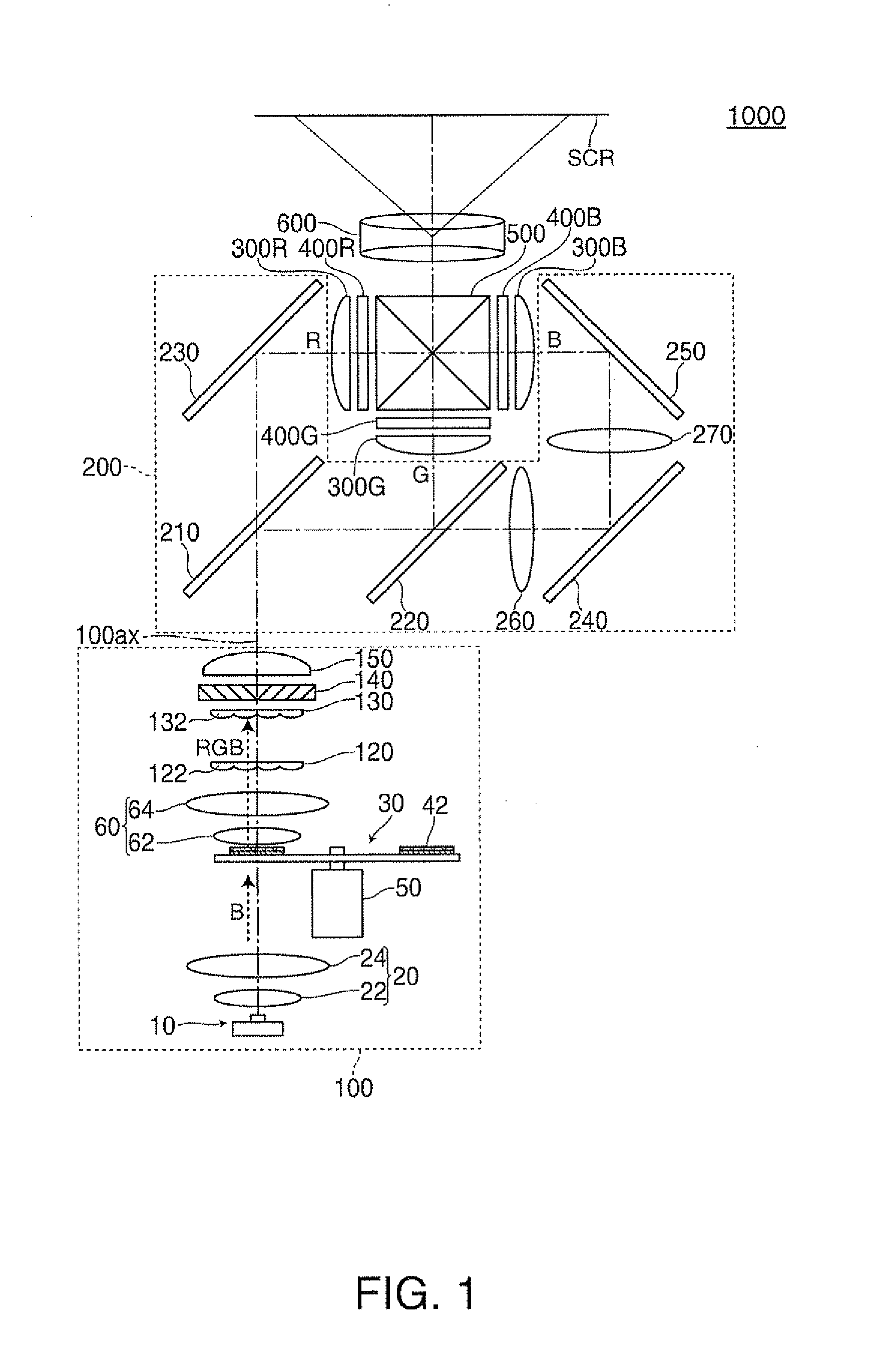
[0058]FIG. 1 is a top view showing an optical system of a projector 1000 according to a first embodiment of the invention. It should be noted that in FIG. 1, in order for making the explanation easy, the constituents of the rotating fluorescent plate 30 are illustrated with the thickness thereof exaggerated. The same can be applied to the drawings mentioned later.

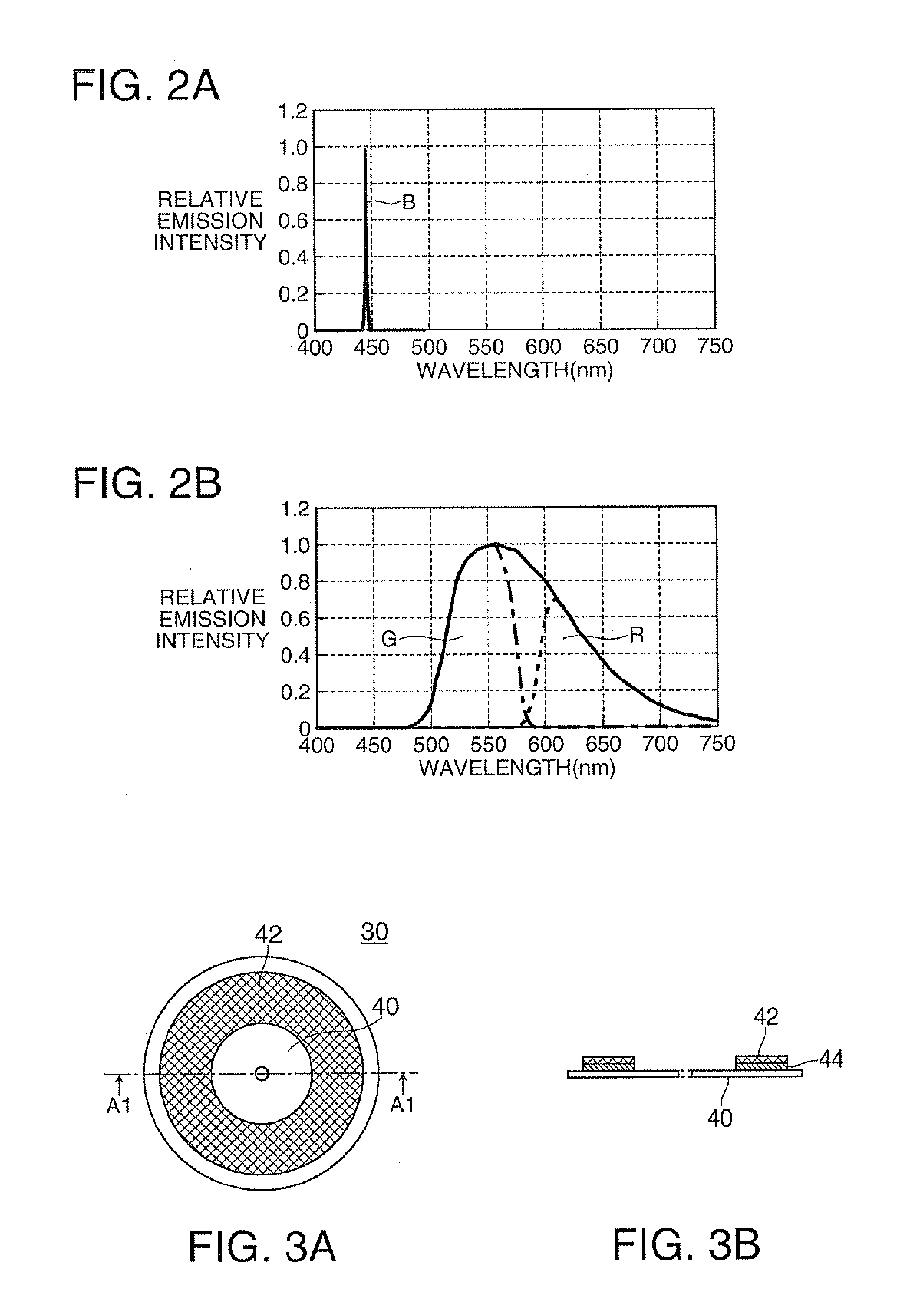
[0059]FIGS. 2A and 2B are graphs showing the emission characteristics of a light source device 10 and a fluorescent layer 42 in the first embodiment. FIG. 2A is a graph showing the emission characteristics of the light source device 10, and FIG. 2B is a graph showing the emission characteristics of the fluorescent layer 42. The emission characteristics denotes the characteristics of the light source device regarding the wavelength and the intensity of the light emitted therefrom in response to application of the voltage, or the characteristics of the fluorescent material regarding the wavelength and the intensity of the lig...

second embodiment

[0109]FIG. 4 is a top view showing an optical system of a projector 1002 according to a second embodiment of the invention.

[0110]FIG. 5 is a graph showing the emission characteristics of a second light source device 710 in the second embodiment. It should be noted that since the emission characteristics of the light source device 10 and the fluorescent layer 46 in the second embodiment are substantially the same as the emission characteristics of the light source device 10 and the fluorescent layer 42 in the first embodiment, the graphical representation will be omitted.

[0111]The projector 1002 according to the second embodiment basically has substantially the same configuration as the configuration of the projector 1000 according to the first embodiment, but is different from the projector 1000 according to the first embodiment in the configuration of the illumination device 102, and in the point that a second illumination device is further provided. Specifically, in the projector ...

third embodiment

[0134]FIG. 6 is a top view showing an optical system of a projector 1004 according to a third embodiment of the invention.

[0135]FIGS. 7A and 7B are diagrams for explaining the rotating fluorescent plate 34 in the third embodiment. FIG. 7A is a front view of the rotating fluorescent plate 34, and FIG. 7B is a cross-sectional view along the line A2-A2 shown in FIG. 7A.

[0136]The illumination device 104 according to the third embodiment basically has a configuration similar to the illumination device 102 according to the second embodiment, but is different from the illumination device 102 according to the second embodiment in the configuration of the rotating fluorescent plate.

[0137]Specifically, in the rotating fluorescent plate 34 in the third embodiment, as shown in FIGS. 7A and 7B, the fluorescent layer 46 is formed on the circular disk 40 via a reflecting film 45 for reflecting visible light (a so-called reflective rotating fluorescent plate), and is configured so as to emit the fl...


PUM


Abstract

An illumination device includes: a light source device adapted to emit an excitation light beam; and a rotating fluorescent plate having a single fluorescent layer adapted to convert a part or whole of the excitation light beam into a fluorescent light beam. The fluorescent light beam includes two or more colored light beams, and the single fluorescent layer is formed on a circular disk, which can be rotated by a motor, continuously along a circumferential direction of the circular disk.

Description

BACKGROUND[0001]1. Technical Field[0002]The present invention relates to an illumination device and a projector.[0003]2. Related Art[0004]In the past, as an illumination device used for a projector, there has been known an illumination device having a light source device for emitting the excitation light (blue light), and a rotating fluorescent plate obtained by providing three segment areas to a circular disk, which can be rotated by an electric motor, and is provided with two types of fluorescent layers emitting light beams with respective colors different from each other (a red light beam and a green light beam) respectively in the two segment areas thereof (see, e.g., JP-A-2009-277516). It should be noted that the remaining segment area out of the three segment areas provided with no fluorescent layer is provided with a scattering layer for scattering the excitation light (the blue light) at a predetermined scattering intensity.[0005]According to the illumination device of the r...

Claims


Application Information

Patent Timeline
IPC IPC(8): G03B21/14F21V9/16
CPCG02B7/008G02B26/007G03B21/142G03B33/08F21V9/08G03B21/204G02B26/008G03B21/28G03B33/12H04N2209/043
Inventor SAKATA, HIDEFUMIKAMIJIMA, SHUNJIMIYAMAE, AKIRANARIMATSU, SHUJI
Owner SEIKO EPSON CORP
Why Eureka
Try Eureka